1. Introduction: The Impact of Vibration on Precision
In the pursuit of sub-micron tolerances and mirror-like surface finishes, Vibration remains the most persistent adversary of the grinding process. Unlike other machining operations, grinding involves a high-frequency interaction between millions of undefined abrasive cutting edges and the workpiece. Any instability in this interaction translates directly into Surface Roughness (Ra) defects and geometric inaccuracies. To achieve true Quality Stability, an engineer must move beyond treating vibration as a single symptom and instead analyze it through a bifurcated lens: Structural vs. Process-Induced effects.
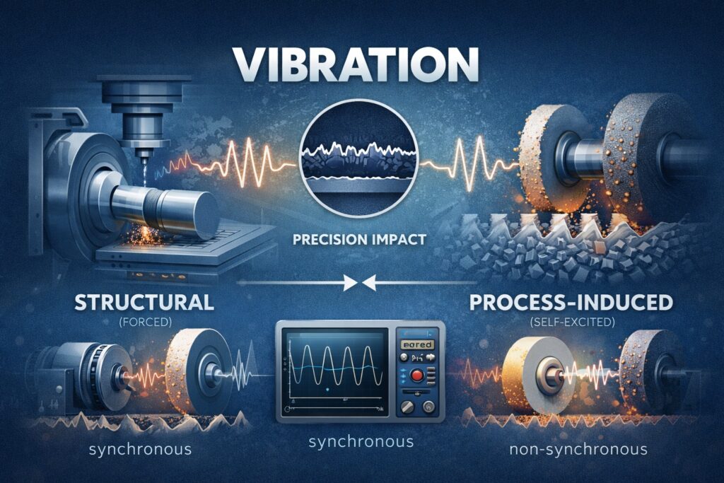
Defining the Dichotomy: Forced vs. Self-Excited Vibration
The distinction between structural and process-induced vibration is fundamental to effective diagnostics. Structural Vibrations, often categorized as forced vibrations, originate from physical imbalances within the machine or external environmental factors. In contrast, Process-Induced Vibrations—commonly known as self-excited vibrations or “chatter”—arise from the dynamic instability of the cutting process itself. Distinguishing between these two is the first step in a deterministic approach to vibration control, as a structural solution (like a damper) will rarely fix a process-induced problem (like regenerative chatter).
The Mechanism of Quality Degradation
When vibration occurs, the relative displacement between the grinding wheel and the workpiece fluctuates, leading to a non-uniform material removal rate. This variation manifests as visible patterns on the surface, such as longitudinal lines or spiral marks, which compromise the component’s Surface Integrity. Furthermore, sustained vibration accelerates the wear of the abrasive grains and the deterioration of the high-precision spindle bearings. Understanding the root cause is therefore not just a quality concern, but a critical factor in extending the Life-cycle of the entire machine tool.
A(t) = Astructural sin(ωft + φ1) + Aprocess eγt sin(ωct + φ2)
Equation 1.1: Superposition of Forced (Structural) and Self-Excited (Process) Vibration Amplitudes
This article provides an exhaustive technical analysis of the various vibration sources encountered in precision grinding. By dissecting the mechanical foundations of structural instability and the dynamic complexities of the cutting arc, we offer a framework for identifying, quantifying, and mitigating vibration to ensure consistent Dimensional Accuracy in modern production environments.
| Vibration Category | Primary Source | Observed Impact |
|---|---|---|
| Structural (Forced) | Wheel unbalance, spindle motor, external floor vibrations. | Synchronous marks; periodic geometric form errors. |
| Process-Induced | Regenerative chatter, wheel loading, infeed dynamics. | High-frequency chatter marks; poor surface finish (Ra). |
| Damping Deficit | Insufficient machine stiffness or bed material quality. | Amplification of small disturbances into resonant oscillations. |
2. Structural Vibration Sources: The Foundation of Instability
Structural Vibrations in a grinding machine are predominantly “forced” in nature, meaning they are driven by an external or internal energy source at a specific frequency. These vibrations exist independently of the cutting forces, although they are often amplified once the wheel engages the workpiece. Identifying these sources requires a precise frequency domain analysis, as the vibration peaks typically coincide with the rotational frequencies of the machine’s primary components.
Wheel and Spindle Unbalance: The 1X Frequency Component
The most common source of structural vibration is Mechanical Unbalance in the grinding wheel assembly. Because grinding wheels are porous and can absorb coolant unevenly, their center of mass often shifts during operation. This creates a centrifugal force that oscillates at the spindle’s rotational frequency (1X). If not corrected via dynamic balancing, this vibration induces a periodic wave on the workpiece surface, leading to “lobing” or “out-of-roundness” errors that compromise Dimensional Accuracy.
External Transmission and Environmental Noise
Precision grinding machines are highly sensitive to Environmental Vibrations transmitted through the factory floor. Heavy machinery, forklifts, or even overhead cranes operating nearby can introduce low-frequency disturbances into the machine bed. Without adequate vibration isolation—such as pneumatic mounts or a dedicated deep-foundation “inertia block”—these external signals bypass the machine’s damping systems and manifest as inconsistent Surface Integrity issues that vary depending on the time of day or factory activity.
Fcentrifugal = m × e × ω2
Equation 2.1: Centrifugal Force Mechanism of Unbalance (m: Mass, e: Eccentricity, ω: Angular Velocity)
Bearing Defects and Gear Mesh Harmonics
Mechanical wear within the spindle Bearings (such as pitting on the inner or outer races) generates high-frequency “ringing” vibrations. These frequencies are distinct from the 1X rotational speed and are calculated based on the bearing geometry. Similarly, in machines utilizing geared drives, the tooth-mesh frequency can introduce micro-vibrations that affect the Quality Stability of the finishing pass. Identifying these harmonics early is vital for predictive maintenance and preventing catastrophic spindle failure.
| Structural Source | Frequency Pattern | Geometric Consequence |
|---|---|---|
| Wheel Unbalance | 1X Spindle RPM (Synchronous). | Periodic waves, out-of-roundness, “waviness”. |
| Bearing Pitting | High-frequency (Non-synchronous). | High-frequency ripples, localized finish degradation. |
| Floor Vibration | Random or Low-frequency (External). | Inconsistent surface finish, non-repetitive errors. |
| Motor Misalignment | 2X or 3X Spindle RPM. | Geometric form error, vibration in coupling housing. |
3. Process-Induced Vibration: The Dynamics of the Cut
Unlike structural vibrations, Process-Induced Vibrations are dynamic instabilities born from the interaction between the abrasive tool and the workpiece. These are often non-synchronous and can develop spontaneously even in a perfectly balanced machine. The most notorious form is Regenerative Chatter, a self-reinforcing phenomenon where the vibration at a previous pass creates waves on the surface that modulate the cutting force in the current pass.
The Regenerative Chatter Mechanism
Regenerative chatter occurs when the phase shift between successive grinding passes creates a variation in the Depth of Cut. If the system’s dynamic stiffness is insufficient to dampen these force fluctuations, the vibration amplitude grows exponentially. In grinding, this can occur on both the workpiece and the grinding wheel itself. “Wheel chatter” is particularly problematic, as the uneven wear patterns on the wheel’s circumference act as a permanent source of excitation, requiring a dressing cycle to restore Dimensional Accuracy.
Wheel Loading and Variable Cutting Forces
As the grinding process continues, metal swarf can become embedded in the wheel’s pores—a condition known as Wheel Loading. This alters the local friction and cutting physics, leading to inconsistent forces across the contact arc. These fluctuating forces act as a stochastic trigger for vibration. Similarly, the dulling of abrasive grains (attritious wear) increases the “rubbing” component of the energy, shifting the process from a stable cutting zone into an unstable friction-dominated zone that promotes high-frequency chatter.
F(t) = kc × [u(t) – u(t – T)] + c × du/dt
Equation 3.1: Simplified Regenerative Force Model (u: Displacement, T: Time delay of one revolution)
Infeed Dynamics and Stability Lobes
The stability of the grinding process is highly dependent on the Material Removal Rate (MRR). Each machine-tool-workpiece combination has specific “Stability Lobes”—regions of spindle speed and depth-of-cut where the process is inherently stable. Operating outside these lobes triggers process-induced vibrations that cannot be solved by balancing alone. To maintain Quality Stability, operators must often adjust the work-head speed or infeed rate to move the process back into a stable machining window.
| Process-Induced Factor | Causal Physics | Diagnostic Symptom |
|---|---|---|
| Regenerative Chatter | Force modulation due to overlapping waves on surface. | Regularly spaced, high-frequency “chatter marks”. |
| Workpiece Burn-Induced | Thermal expansion of workpiece causing force spikes. | Sudden onset of vibration accompanied by discoloration. |
| Wheel Dullness | Transition from cutting to rubbing/plowing forces. | Gradual increase in vibration amplitude over a batch. |
| Infeed Overload | Exceeding the static and dynamic stiffness of the machine. | Low-frequency structural growl or screeching sound. |
4. Diagnostic Mechanisms: Identifying the Root Cause
Solving a vibration issue in precision grinding requires more than just intuition; it demands a systematic Diagnostic Mechanism. The first step is to determine whether the vibration is synchronous (linked to machine rotation) or non-synchronous (linked to process instability). By utilizing Fast Fourier Transform (FFT) analysis, engineers can decompose complex time-domain signals into their constituent frequencies, allowing for the precise identification of the offending component.
Frequency Domain Analysis: Synchronous vs. Asynchronous
The most reliable diagnostic mechanism is comparing the measured vibration peaks with the known rotational frequencies of the machine. If a dominant peak appears at exactly 50 Hz on a spindle running at 3,000 RPM, the cause is undoubtedly Structural Unbalance. However, if the vibration frequency shifts as the depth of cut increases or if it appears at a high-frequency multiple that does not match any mechanical rotation, it is a clear signature of Regenerative Chatter.
The “Impact Test” for Structural Resonance
Often, a vibration problem is exacerbated by the machine’s own natural frequencies. Using a calibrated impact hammer and an accelerometer, an engineer can perform a Frequency Response Function (FRF) test. This mechanism identifies the “modal” frequencies where the machine bed or spindle assembly is most prone to oscillation. If the operational frequency of the process happens to coincide with these natural modes, resonance occurs, amplifying minor disturbances into catastrophic Surface Integrity failures.
fvibration = (n × RPM) / 60 ± fchatter
Equation 4.1: Frequency Correlation for Synchronous (n=integers) and Non-synchronous Components
Variable Speed Testing: Confirming the Source
A simple yet effective diagnostic mechanism is the variable speed test. By incrementally changing the wheel speed while monitoring the vibration amplitude, one can distinguish between forced and self-excited sources. Forced vibrations (like unbalance) will change in frequency but their relative amplitude typically remains predictable. Self-excited chatter, however, will often disappear or drastically change character at specific “stable” speeds, providing a direct roadmap for optimizing Quality Stability.
| Diagnostic Tool | Operational Mechanism | Root Cause Indication |
|---|---|---|
| FFT Spectrum Analysis | Converts time-domain waves to frequency peaks. | Synchronous peaks = Unbalance; High-freq non-sync = Chatter. |
| Waterfall Plot | Visualizes frequency changes over time or speed. | Identifies transient instabilities and resonance crossing points. |
| Modal Impact Testing | Measures the machine’s structural stiffness/damping. | Pinpoints weak structural points and natural frequencies. |
| Bump Test | Briefly excites the spindle without cutting. | Distinguishes motor-induced noise from process-induced chatter. |
5. Mitigation Strategies: Restoring Quality Stability
Once the root cause of vibration has been identified, the focus shifts to Mitigation Strategies. Successfully restoring Quality Stability requires a dual-track approach: mechanical remediation for structural issues and parameter optimization for process-induced instability. These strategies aim to either eliminate the excitation source or increase the system’s dynamic damping capacity to prevent the amplification of oscillations.
Dynamic Balancing and Structural Damping
For structural vibrations, the primary solution is Dynamic Balancing. Modern grinding centers often utilize integrated auto-balancers that compensate for wheel unbalance in real-time. If the vibration is transmitted through the floor, installing high-performance anti-vibration mounts or utilizing a mineral cast bed (Granitan) can significantly improve the Damping Capacity. Mineral casting offers up to 10 times the damping of traditional gray cast iron, effectively absorbing the energy from forced vibrations before it reaches the tool-workpiece interface.
Suppressing Chatter via Parameter Modulation
To mitigate Process-Induced Chatter, the most effective strategy is the disruption of the regenerative feedback loop. This can be achieved through Spindle Speed Variation (SSV), where the RPM is subtly modulated during the cycle to prevent waves from synchronizing. Additionally, selecting a grinding wheel with a non-uniform grit distribution or a “variable pitch” dressing pattern can break the harmonic frequency of the cut, ensuring that the Surface Integrity remains consistent even under aggressive material removal rates.
Glimit ∝ (kstatic × ζdamping) / bwidth
Equation 5.1: Stability Limit Threshold (k: Stiffness, ζ: Damping Ratio, b: Grinding Width)
Precision Dressing and Active Control
A sharp, well-dressed wheel is the best defense against friction-induced vibration. Dressing Optimization ensures that the abrasive grains remain sharp, minimizing the “plowing” force that often triggers self-excited oscillations. For high-end applications, Active Vibration Control systems utilize piezoelectric actuators to generate counter-vibrations, effectively canceling out chatter in real-time. This level of control is essential for maintaining Dimensional Accuracy in the manufacturing of aerospace and semiconductor components.
| Strategy Type | Specific Action | Expected Precision Benefit |
|---|---|---|
| Mechanical | Auto-balancing and high-damping bed materials. | Reduction of periodic synchronous waviness (1X). |
| Kinematic | Spindle Speed Variation (SSV) and infeed adjustment. | Elimination of high-frequency regenerative chatter. |
| Tooling | Increased dressing frequency or variable pitch wheels. | Lower cutting forces; prevented wheel loading instability. |
| Advanced | Active piezoelectric damping and AI monitoring. | Real-time adaptation to changing process dynamics. |
6. Conclusion: Achieving a Vibration-Free Process
As we have explored, Vibration in precision grinding is not an inevitable byproduct of the process, but a manageable engineering variable. The distinction between Structural and Process-Induced effects is the foundation of any successful troubleshooting effort. By shifting from reactive trial-and-error to a deterministic diagnostic approach, manufacturers can transform vibration from a source of scrap into a metric for process optimization.
The Holistic Approach to Quality Stability
Achieving a vibration-free process requires the harmonization of the entire machining ecosystem. High-damping bed materials and dynamic balancing systems provide the necessary Structural Integrity, while optimized dressing and infeed parameters ensure Process Stability. When these elements are perfectly aligned, the result is not just a superior Surface Roughness (Ra), but a significantly extended life-cycle for the spindle bearings and the abrasive tools themselves.
Future Outlook: AI and Real-Time Adaptive Control
The next frontier in vibration management lies in Autonomous Diagnostics. Integration with the Industrial Internet of Things (IIoT) allows for continuous vibration monitoring via high-fidelity sensors. Future grinding centers will utilize AI algorithms to predict the onset of regenerative chatter before it becomes visible on the workpiece, automatically adjusting spindle speeds or feed rates to remain within the “Stability Lobe.” This evolution toward a self-healing process will be the ultimate guarantee for Dimensional Accuracy in the era of smart manufacturing.
Mastering the Dynamics of Precision
“Vibration control is the bridge between a functional machine and a world-class manufacturing system. True precision is the silence of a perfectly tuned process.”
References & Technical Resources
- • Altintas, Y. (2012). Manufacturing Automation: Metal Cutting Mechanics, Machine Tool Vibrations, and CNC Design. Cambridge University Press.
- • Inasaki, I. (2001). Vibration in Grinding and Its Control. Journal of the Japan Society for Precision Engineering.
- • Tlusty, J. (2000). Manufacturing Processes and Equipment. Prentice Hall.
Internal Technical Deep-Dive
To further integrate your understanding of machine dynamics and vibration control within the broader scope of precision manufacturing, please refer to the following modules from our library:
VIBRATION ANALYSIS:
Why Does Chatter Occur in Grinding? Vibration Mechanisms Explained
STRUCTURAL RIGIDITY:
Machine Stiffness in Grinding: Why Structural Rigidity Affects Surface Quality
SPINDLE DESIGN:
Grinding Spindle Design: Bearing Type, Speed Range, and Heat Generation
PROCESS STABILITY:
Grinding Process Stability: Why Stable Processes Reduce Total Manufacturing Cost