1. Introduction: The Thermal Management in Grinding
In the abrasive process, the grinding zone acts as a high-intensity heat generation source. Because grinding involves negative rake angle cutting and high-speed friction, nearly 80% to 90% of the energy consumed is converted into thermal energy. Without an engineered Coolant System, this heat would lead to catastrophic surface damage, including metallurgical burn, residual tensile stress, and accelerated wheel wear. Therefore, the coolant system is not merely a peripheral accessory but a primary stabilization system that dictates the boundaries of productivity and precision.
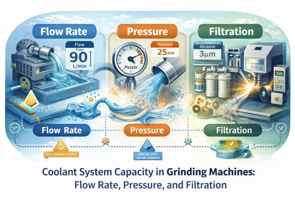
The Trifecta of Coolant Capacity: Flow, Pressure, and Purity
Defining the System Capacity requires a deterministic analysis of three interlinked variables: Flow Rate, Pressure, and Filtration Efficiency. Each factor serves a distinct role in the process. The flow rate ensures the volume of fluid is sufficient to carry away the massive thermal flux, while the delivery pressure is responsible for penetrating the high-velocity air barrier surrounding the rotating wheel. Lastly, the filtration system ensures that recycled fluid does not re-introduce abrasive grit and metal swarf back into the grinding interface, which would compromise Surface Integrity.
Beyond Cooling: Lubrication and Chip Flushing
The coolant’s function extends beyond simple temperature regulation. It acts as a critical lubricant, reducing the coefficient of friction between the grit and the workpiece, thereby lowering the total grinding energy required. Simultaneously, the system provides a flushing effect to clear chips from the grinding wheel’s pores. If the system capacity is insufficient to evacuate these chips, the wheel will load, causing a rapid increase in grinding forces and a subsequent loss of Dimensional Accuracy.
Qcoolant = (Pgrinding × kthermal) / (ρ × Cp × ΔT)
Equation 1.1: The Minimum Required Flow Rate (Q: Flow, P: Power, k: Heat Fraction)
As manufacturers push for High-Efficiency Deep Grinding (HEDG) and tighter Quality Stability, the traditional “more is better” approach to coolant is no longer viable. An optimized System Specification is required to balance energy consumption with process reliability. This article will dissect the internal functions of coolant delivery and filtration, providing a technical framework for selecting the right system capacity for high-precision operations.
| Design Pillar | Technical Focus | Operational Impact |
|---|---|---|
| Flow Rate | Total volume delivery (L/min) based on grinding power. | Determines the thermal dissipation capacity of the process. |
| Delivery Pressure | Nozzle exit velocity and penetration energy. | Overcomes the air barrier to ensure fluid reaches the contact zone. |
| Filtration Grade | Contaminant removal (Micron rating) and fluid clarity. | Prevents secondary damage and maintains surface finish quality. |
2. Flow Rate Optimization: Engineering the Thermal Sink
The determination of Flow Rate is a deterministic engineering task based on the thermodynamic requirements of the grinding zone. The primary objective is to provide a thermal sink capable of absorbing the specific grinding energy (SGE) before the fluid reaches its boiling point. If the flow rate is insufficient, the coolant undergoes film boiling, creating a vapor barrier that leaves the workpiece vulnerable to instantaneous metallurgical damage.
Specific Grinding Energy and Volumetric Requirements
To calculate the precise flow requirement, one must consider the material removal rate (MRR) and the specific energy of the material being ground. In high-precision environments, a reliable benchmark is to deliver 8 to 12 liters per minute for every kilowatt of power consumed at the spindle interface. This ratio is designed to limit the coolant temperature rise (ΔT) to less than 5°C, ensuring that the machine’s geometric loop remains stable and preventing the expansion of the workpiece during the cycle.
Nozzle Velocity Synchronization and Air Barrier Breakthrough
Total system flow is ineffective if the fluid cannot penetrate the high-velocity air barrier generated by the rotating wheel. A grinding wheel acts as a centrifugal fan, creating a boundary layer of air that can deflect low-velocity coolant streams. Therefore, the nozzle exit velocity must be engineered to match or slightly exceed the peripheral speed of the wheel (Vs). This synchronization ensures that the kinetic energy of the coolant is sufficient to displace the air barrier and flood the actual contact arc.
Qmin = (Pspindle × ηthermal) / (ρ × Cp × ΔTallowed)
Equation 2.1: Thermodynamic Flow Rate Calculation (η: Thermal fraction to fluid)
Flow Consistency and System Pressure Stability
Achieving the target flow rate requires a pump capable of maintaining pressure against the cumulative resistance of the filtration system and the nozzle orifice. As filters accumulate swarf, back-pressure increases; a robust system must utilize variable frequency drives (VFD) to adjust pump speed and maintain a constant volumetric flow. Monitoring “Flow per Unit Width” of the wheel is the industry standard for ensuring consistent cooling across the entire active abrasive surface.
| Process Variable | Engineering Specification | Impact on Process Stability |
|---|---|---|
| Specific Flow Ratio | 8 – 12 L/min per kW of Spindle Power. | Prevents film boiling and metallurgical burn on the workpiece. |
| Nozzle Exit Velocity | Matched to 0.9 – 1.1x of Wheel Peripheral Speed (Vs). | Ensures the air barrier breakthrough and saturation of the contact arc. |
| Thermal Gradient (ΔT) | Targeted ΔT rise < 5°C in the bulk fluid. | Maintains geometric loop integrity and dimensional consistency. |
| Effective Width Flow | Minimum 25 L/min per 10mm of Grinding Wheel Width. | Guarantees uniform cooling and prevents localized thermal stress. |
3. Pressure and Velocity: The Kinetic Energy of Coolant
In the context of a high-performance coolant system, Delivery Pressure is not merely a measure of pump force; it is the primary driver of the fluid’s kinetic energy. While flow rate provides the volumetric heat sink, it is the velocity—derived directly from the system pressure—that determines whether that volume actually reaches the grinding zone. Without sufficient pressure, the coolant cannot overcome the mechanical and aerodynamic barriers present at the tool-workpiece interface.
The Air Barrier Breakthrough and Kinetic Dominance
As a grinding wheel rotates at high speeds (e.g., 30–120 m/s), it acts as a centrifugal blower, creating a stiff, high-velocity Air Barrier. This boundary layer of air can effectively “shield” the contact arc from low-pressure coolant streams. To break through this barrier, the coolant jet must possess a velocity (Vj) that matches or exceeds the peripheral speed of the wheel (Vs). This requires a calculated pump pressure (P) that accounts for nozzle orifice efficiency and frictional losses in the plumbing.
Pore Penetration and Lubrication Delivery
Beyond breaking the air barrier, high-velocity coolant must also penetrate the Pore Structure of the grinding wheel. High-pressure delivery (typically 15 to 40 bar depending on the application) forces the fluid into the chip gullets between abrasive grains. This ensures that the lubricant is present at the exact moment of engagement, reducing the coefficient of friction and preventing the premature “loading” of the wheel with metal swarf. In Creep-feed grinding, this penetration is the difference between a stable process and instantaneous thermal failure.
Vj (m/s) = φ × √(2 × P / ρ)
Equation 3.1: Coolant Jet Velocity Calculation (φ: Nozzle Coefficient, P: Pressure in Pascals)
Nozzle Design and Coherent Jet Stability
Pressure alone is insufficient if the resulting jet is turbulent or divergent. High-quality Coherent Nozzles are engineered to maintain a laminar flow profile, preventing the coolant from atomizing into a mist before it hits the target. A stable, coherent jet concentrates the kinetic energy on the contact zone, allowing for a lower total flow volume while achieving superior cooling efficiency. This precision delivery is essential for maintaining Dimensional Consistency in automated production lines.
| Pressure Category | Operating Range (Bar) | Primary Technical Objective |
|---|---|---|
| Low Pressure (Flushing) | 1 – 5 Bar | General chip removal and bulk machine temperature stabilization. |
| Standard Grinding | 10 – 25 Bar | Breaking the air barrier at Vs ≤ 45 m/s; ensuring wheel saturation. |
| High-Pressure Deep Grinding | 30 – 70+ Bar | High-velocity HEDG operations; intensive cleaning of superabrasive wheels. |
| Hydro-Cleaning | 70 – 150 Bar | Active removal of “loaded” metal from wheel pores to maintain sharpness. |
4. Filtration Systems: Maintaining Fluid Integrity
In a high-precision grinding environment, the coolant is a recirculating medium that carries a high concentration of abrasive grit and metal swarf. If the Filtration System fails to remove these particulates, the coolant becomes a slurry of abrasive contaminants. This leads to secondary scratching of the workpiece—often referred to as “comet tails”—and accelerated wear of the high-pressure pump components. Achieving Quality Stability requires a filtration strategy that matches the particle size distribution (PSD) of the grinding debris to the specific finish requirements.
Filtration Mechanisms and Micron Ratings
The selection of a Filtration Grade is dictated by the desired surface roughness (Ra). For general surface grinding, a filtration level of 20 to 30 microns is typically sufficient. However, for ultra-precision applications where mirror finishes are required, the system must achieve a 1 to 5-micron rating. This is often accomplished through multi-stage filtration: primary separation via magnetic drums or cyclones, followed by secondary polishing through paper media or back-flushable ceramic filters.
Managing Sludge and Coolant Life-cycle
Effective filtration also plays a critical role in the chemical stability of the fluid. Fine metallic particles have a high surface-area-to-volume ratio, which promotes the oxidation of the metal and the depletion of the coolant’s anti-corrosion additives. A high-capacity Sludge Removal system prevents the accumulation of “fine fines” that can bypass standard filters and clog the precision orifices of coherent nozzles, causing a catastrophic drop in flow rate and pressure at the point of cut.
βx = Nupstream / Ndownstream
Equation 4.1: The Beta Ratio (β) – Filter Efficiency Evaluation for Particle Size ‘x’
The Impact on Spindle and Pump Reliability
Poor filtration is the leading cause of “stiction” in hydraulic valves and premature failure of internal coolant-fed spindles. Abrasive particles as small as 10 microns can erode the precision seals of high-pressure pumps, leading to a gradual loss of System Pressure that is often difficult to detect until a part is scrapped. Modern intelligent systems now integrate differential pressure sensors across the filter media to automate the indexing or cleaning cycle, ensuring Dimensional Consistency throughout 24/7 production.
| Filtration Type | Typical Micron Rating | Precision Outcome |
|---|---|---|
| Magnetic Separator | 30 – 50+ μm | Primary ferrous removal; prevents bulk pump erosion. |
| Paper Band Filter | 10 – 25 μm | Standard finishing; removes non-ferrous grit and swarf. |
| Hydrocyclone | 5 – 10 μm | High-speed centrifugal cleaning; consistent fluid clarity. |
| Cartridge/Ceramic | 1 – 3 μm | Ultra-precision finishing; prevents micro-scratches on optics. |
5. Tank Capacity and Thermal Stability
The physical dimensions of a Coolant Tank are a critical factor in maintaining the long-term accuracy of a grinding center. While flow and pressure address the immediate needs of the grinding zone, the tank capacity governs the Thermal Inertia of the entire system. A tank that is too small will cause the fluid temperature to rise rapidly, leading to the expansion of the machine casting and a subsequent drift in Dimensional Accuracy. Mastering the relationship between volume and temperature is essential for high-precision batch production.
The Rule of Residence Time: De-aeration and Sedimentation
Effective tank design must provide sufficient Residence Time for the fluid. As coolant returns from the machine, it is often aerated and carries fine suspended particles. If the tank volume is insufficient, the fluid is recirculated before the air bubbles can escape. Entrained air reduces the fluid’s heat-carrying capacity and can cause cavitation in high-pressure pumps. An industry-standard tank should hold 5 to 10 times the system’s maximum flow per minute to allow for proper de-aeration and the natural sedimentation of heavy swarf.
Thermal Equilibrium and Active Chilling
In ultra-precision grinding, the coolant temperature must be synchronized with the machine’s ambient environment, typically within ±0.1°C. An undersized tank forces the Chiller System to cycle frequently, creating thermal oscillations that manifest as periodic form errors on the workpiece. A larger fluid volume acts as a thermal buffer, dampening these fluctuations and ensuring that the Quality Stability of the process remains uncompromised even during intensive material removal cycles.
tresidence (min) = Vtank / Qtotal ≥ 10 minutes (Optimal)
Equation 5.1: Minimum Residence Time for Air Escape and Thermal Buffering
Baffle Design and Flow Dynamics
The internal geometry of the tank is as important as its volume. High-performance systems utilize a series of Baffles to create a serpentine flow path. This ensures that the returning “hot” and “dirty” fluid does not immediately reach the “clean” pump intake. This managed flow path maximizes the contact time with the tank walls for passive cooling and provides a stable environment for oil-skimmers to remove tramp oil, which is a leading cause of bacterial growth and fluid degradation.
| System Variable | Standard Specification | Stability Outcome |
|---|---|---|
| Tank Volume Ratio | 5x to 10x Max Flow Rate. | Prevents rapid temperature spikes and pump cavitation. |
| Active Chilling | Ambient ± 0.5°C (Precision: ± 0.1°C). | Eliminates dimensional drift over long production shifts. |
| Tramp Oil Skimming | Disc or Belt type at the “Quiescent” zone. | Reduces bacterial odor and extends fluid service life. |
| Sedimentation Area | Low-velocity section before filtration. | Reduces the load on primary filter media; lowers cost. |
6. Conclusion: Engineering a Balanced System
A high-performance coolant system is far more than a simple delivery pump; it is a meticulously engineered thermal and hydraulic system that directly defines the limits of a grinding process. As we have explored, the synergy between Flow Rate, Pressure, and Filtration Efficiency is what creates a stable environment for precision manufacturing. Failing to balance any one of these variables leads to a compromise in either productivity, tool life, or the final Surface Integrity of the workpiece.
The Shift Toward Intelligent Coolant Management
The future of abrasive machining lies in the transition from “flooding” to “precision targeting.” Modern intelligent systems now utilize Sensor-Based Monitoring to adjust flow and pressure in real-time based on the actual power consumption at the spindle. This not only reduces the energy footprint of the high-pressure pumps but also ensures that the Quality Stability is maintained even as the wheel diameter decreases and the contact kinematics shift.
Sustainability and Minimal Quantity Lubrication (MQL)
As environmental regulations tighten, the industry is increasingly looking toward Green Grinding technologies. Technologies such as MQL and cryogenic cooling aim to achieve the same thermal results with a fraction of the fluid volume. However, for high-stock removal operations, the System Capacity of traditional water-based coolants remains the gold standard for its superior heat extraction capability. The key for future mastery lies in maximizing the efficiency of every drop through optimized nozzle geometry and advanced filtration mechanisms.
The Science of Thermal Control
“In precision grinding, we do not just manage fluid; we manage energy. A balanced coolant system is the primary insurance against the invisible thermal errors of manufacturing.”
References & Technical Resources
- • Marinescu, I. D., et al. (2015). Handbook of Machining with Grinding Wheels. CRC Press.
- • Webster, J., & Tricard, M. (2004). Innovations in Grinding Wheel Dressing and Coolant Application. CIRP Annals.
- • Brinksmeier, E., et al. (2006). Coolant Supply in Grinding: Research and Practice. Production Engineering.
Internal Technical Deep-Dive
To further integrate your understanding of coolant system specifications and their impact on grinding performance, please refer to the following modules from our technical library: