1. Introduction: The Deterministic Nature of Control Accuracy
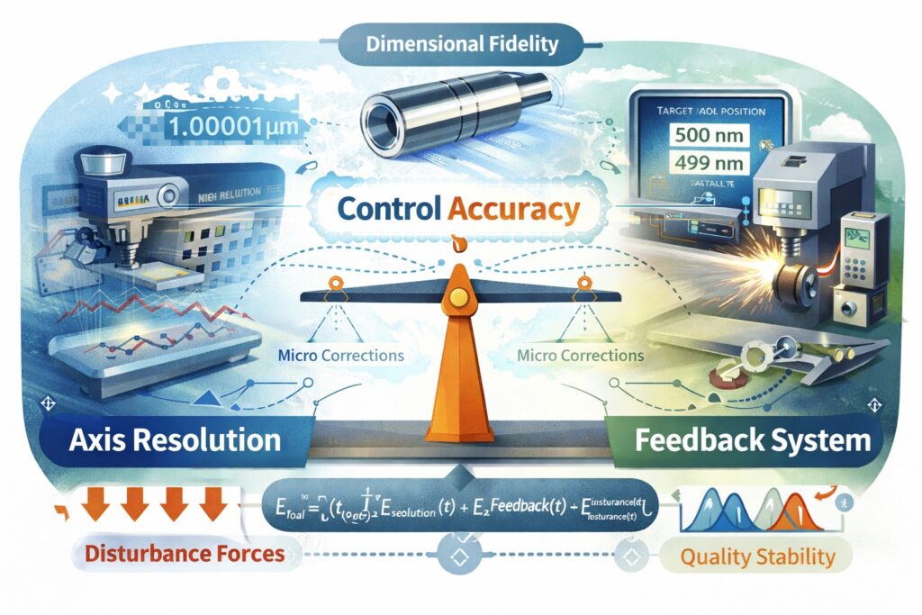
In the hierarchy of high-precision manufacturing, the grinding machine represents the final frontier of Dimensional Fidelity. Unlike milling or turning, where micron-level variances may be tolerable, precision grinding operates in a domain where sub-micron deviations define the boundary between a functional component and scrap. At the center of this capability is Control Accuracy—the system’s ability to execute a programmed command with absolute reliability under dynamic loads. This is an emergent property derived from the synergy between Axis Resolution and Feedback Systems.
The Resolution Threshold and Motion Fidelity
Axis Resolution serves as the fundamental quantization level of the positioning system. It is the smallest addressable increment that the CNC controller can command and the drive system can theoretically execute. In modern grinding centers, resolution is a complex mechanism governed by the encoder’s bit-depth, the lead of the ballscrew, and the interpolation capabilities of the servo drive. Without a sufficiently high resolution, the control system cannot perform the micro-corrections required to counteract abrasive forces, leading to a direct loss of Quality Stability.
Feedback Loops: Bridging the Gap Between Command and Reality
No mechanical structure is perfectly rigid or thermally invariant. External factors such as thermal drift and varying grinding forces act as a constant error-induction mechanism. The Feedback System serves as the machine’s critical corrective interface, monitoring the actual position of the axes in real-time. By utilizing a closed-loop mechanism, the machine compares the commanded position with the physical state, allowing the controller to compensate for structural elasticities. This real-time synchronization is the only way to ensure that Control Accuracy remains consistent throughout the entire production cycle.
ETotal = ∫ [EResolution(t) + EFeedback(t) + EDisturbance(t)] dt
Equation 1.1: Cumulative Error Integral and Control Optimization Mechanism
| Control Pillar | Technical Focus | Operational Mechanism Impact |
|---|---|---|
| Axis Resolution | Density of addressable points from encoder bit-depth and interpolation. | Determines command fidelity and smoothness of micro-feed motion. |
| Feedback System | Direct (Linear) vs. Indirect sensing for real-time verification. | Functions as the primary compensation mechanism for thermal drift. |
| Control Accuracy | Dynamic error minimization through high-bandwidth servo loop tuning. | Directly impacts dimensional consistency and Cpk values. |
2. Axis Resolution: Technical Definition and Physical Constraints
In precision grinding, Axis Resolution is the theoretical floor of the machine’s positioning capability. It defines the minimum programmable increment (MPI) that the control system can distinguish and execute. However, a common misconception in the field is equating high electronic resolution directly with superior Control Accuracy. In reality, resolution is the mechanism that provides the data density required for precision, but its effectiveness is strictly governed by both the electronic quantization of the feedback device and the mechanical transmission limits of the drive train.
The Electronic Quantization Mechanism: Encoder Bit-Depth
The journey toward sub-micron precision begins at the motor’s feedback interface. Modern servo motors utilize high-resolution absolute encoders, typically ranging from 20-bit to 26-bit per revolution. This mechanism divides a single 360-degree rotation into millions of discrete, addressable pulses. For example, a 24-bit encoder provides 16,777,216 pulses per revolution. This extreme data density is essential not only for static positioning but for the smooth calculation of velocity at ultra-low feed rates—a critical factor in achieving nanometer-level Surface Integrity during the spark-out phase of grinding.
Mechanical Transformation: Ballscrew Pitch and Linear Resolution
The rotary motion generated by the motor must be translated into linear displacement through the ballscrew mechanism. The final linear resolution is a direct product of the encoder’s pulse count and the ballscrew pitch. While a finer pitch increases the mechanical advantage and resolution, it simultaneously limits the maximum traverse speed. In high-end grinding centers, the relationship between the lead of the screw and the angular resolution of the motor defines the “granularity” of the axis movement, which must be optimized to prevent quantization noise from manifesting as chatter marks on the workpiece.
Rlinear = L / (2n × Ip)
Equation 2.1: Linear Axis Resolution Mechanism (L: Pitch, n: Encoder Bits, Ip: Interpolation Factor)
Physical Limits: Noise and Mechanical Lost Motion
Indefinitely increasing electronic resolution yields diminishing returns due to the signal-to-noise ratio in the interpolation mechanism. Furthermore, mechanical constraints such as Lost Motion—which includes backlash, pitch error, and elastic deformation of the support bearings—often exceed the theoretical electronic resolution. If a system possesses a 1-nanometer electronic resolution but suffers from 500 nanometers of mechanical backlash, the actual Control Accuracy will be bottlenecked by the hardware. Therefore, a deterministic design must balance electronic bit-density with high-rigidity mechanical components to ensure the resolution is “realizable” at the grinding wheel.
| Resolution Variable | Technical Mechanism | Impact on Control Accuracy |
|---|---|---|
| Encoder Bit-Depth | High-frequency quantization of motor shaft angle. | Increases positioning data density and velocity smoothness. |
| Ballscrew Lead | Mechanical conversion of rotary to linear displacement. | Defines the physical step size and mechanical advantage. |
| Interpolation Error | Sub-division of analog sine/cosine feedback signals. | Can introduce periodic errors affecting surface finish. |
3. Feedback Systems: Comparative Architectures and Control Principles
In the architecture of a precision grinding machine, the Feedback System acts as the sensory mechanism that closes the gap between the commanded position and the actual physical state. Without a robust feedback loop, the control system operates “blind,” unable to account for the inherent elasticities and thermal instabilities of the mechanical structure. The choice between Semi-closed and Full-closed Loop configurations fundamentally determines the machine’s ability to maintain Control Accuracy under varying operational stresses.
Semi-closed Loop Mechanism: Indirect Sensing
The Semi-closed Loop is the most common feedback mechanism in standard CNC machines. Here, the position data is derived from a rotary encoder mounted directly on the servo motor shaft. While this system provides high-bandwidth velocity feedback and excellent stability, it is an Indirect Sensing method. It assumes that the ballscrew and support bearings are perfectly rigid and thermally stable. Consequently, any error introduced by ballscrew thermal expansion, pitch error, or backlash remains undetected by the controller, leading to a degradation in long-term Quality Stability.
Full-closed Loop Mechanism: Direct Linear Feedback
To achieve sub-micron Control Accuracy, high-end grinding machines employ a Full-closed Loop mechanism. This system utilizes a Linear Scale mounted directly to the machine slide, providing Direct Sensing of the actual tool-point position. By bypassing the mechanical transmission errors of the ballscrew and couplings, the linear scale allows the CNC to compensate for real-time thermal drift and mechanical lost motion. This direct feedback mechanism is the only way to ensure that the “commanded micron” is the “delivered micron” at the grinding wheel interface.
Eposition = Pcommand – (Pmotor_encoder + Δtransmission) → Full-closed Corrects Δtransmission
Equation 3.1: Compensation Mechanism for Transmission Error in Full-closed Loop
The Challenge of Servo Lag and Bandwidth
While Full-closed Loop systems offer superior accuracy, they introduce complexity into the servo tuning mechanism. The physical distance between the motor (the actuator) and the linear scale (the sensor) creates a “mechanical delay” or phase shift in the feedback signal. If the machine structure lacks sufficient dynamic stiffness, this delay can lead to servo instability or “hunting” at high gains. Therefore, high Control Accuracy requires not just a precise sensor, but a high-bandwidth control mechanism capable of processing dual-feedback signals—rotary for velocity and linear for position—simultaneously.
| Feedback Architecture | Sensing Mechanism | Accuracy Constraint |
|---|---|---|
| Semi-closed Loop | Rotary Encoder on Motor Shaft. | Vulnerable to ballscrew thermal drift and backlash. |
| Full-closed Loop | Direct Linear Scale on Axis Slide. | Eliminates transmission errors; requires high structural damping. |
| Hybrid Feedback | Combined Rotary (Velocity) and Linear (Position). | Optimizes both dynamic response and absolute positioning. |
4. Mechanical Mechanisms Hindering Control Accuracy
Even with a high-resolution 26-bit encoder and a sub-micron linear scale, the final Control Accuracy of a grinding machine is ultimately limited by the physical behavior of its mechanical components. In the micro-displacement domain, the machine no longer behaves as a perfectly rigid body. Instead, it becomes a complex mechanism of elastic deformations and non-linear friction. Understanding these parasitic effects is essential for developing effective compensation strategies in the CNC controller.
Backlash and Lost Motion Mechanism
Backlash is the inherent clearance between the ballscrew threads and the nut, or within the coupling mechanism. While preloaded double-nuts can minimize this, a certain degree of Lost Motion—the difference between the commanded reversal and the actual physical reversal—always remains. In contour grinding, this mechanism manifests as “quadrant glitches,” where the axis momentarily stalls during a direction change. If the lost motion exceeds the axis resolution, the feedback loop may struggle to stabilize, causing a significant drop in Quality Stability.
Friction and the Stick-Slip Mechanism
At the nanometer scale, the transition from static to dynamic friction becomes a dominant mechanism affecting Control Accuracy. Known as Stick-Slip, this phenomenon occurs when the driving force exceeds static friction, causing a sudden “jump” in position. For grinding machines requiring ultra-fine incremental feeds (0.1 μm or less), stick-slip acts as a non-linear disturbance that even the fastest PID loops find difficult to suppress. This necessitates the use of high-damping mechanisms such as hydrostatic guideways or specialized friction-compensation algorithms in the servo drive.
Fdrive > Fstatic → Δx = (kstructural)-1 × ΔF
Equation 4.1: The Mechanism of Elastic Jump in Stick-Slip Conditions
Thermal Drift: The Time-Dependent Error Mechanism
Thermal expansion is perhaps the most insidious mechanism impacting long-term Control Accuracy. As the grinding spindle and ballscrews generate heat during operation, the axis “grows” in length. A 1-meter steel ballscrew can expand by 12 μm for every 1°C rise in temperature. Without a real-time thermal compensation mechanism—either through active cooling or software-based displacement models—the workpiece dimensions will drift throughout the production shift, undermining the Cpk performance of the process.
| Mechanical Error | Root Mechanism | Impact on Precision |
|---|---|---|
| Backlash | Mechanical clearance in transmission. | Hysteresis and reversal errors in contouring. |
| Stick-Slip | Non-linear friction transition. | Inability to execute micro-increments smoothly. |
| Thermal Expansion | Temperature-induced material growth. | Gradual drift in dimensional accuracy over time. |
5. Servo Control Algorithms: The Core of Dynamic Accuracy
While high-resolution encoders and rigid hardware provide the physical foundation, the “intelligence” of a grinding machine resides in its Servo Control Algorithm. This software-driven mechanism is responsible for calculating the precise current required to move the motor to its target position while simultaneously rejecting external disturbances. In precision grinding, where the interaction between the abrasive wheel and the workpiece creates high-frequency force fluctuations, the optimization of the control loop is the final determinant of Control Accuracy.
Advanced PID and Feed-forward Mechanisms
The traditional Proportional-Integral-Derivative (PID) controller remains the workhorse of axis control. However, for sub-micron accuracy, a standard PID loop is insufficient due to Servo Lag (Following Error). To counteract this, modern grinding CNCs employ Feed-forward Mechanisms. By predicting the required torque based on the commanded velocity and acceleration, feed-forward control reduces the burden on the PID loop, allowing the axis to follow the programmed path with near-zero lag. This is critical for Quality Stability during complex contouring or high-speed reciprocating grinding.
Vibration Suppression and Notch Filter Mechanisms
Every mechanical axis has a natural resonant frequency. When the servo gain is increased to improve Control Accuracy, it often excites these resonances, leading to high-frequency oscillation or “ringing.” To solve this, sophisticated Notch Filter Mechanisms are integrated into the drive electronics. These digital filters specifically attenuate the resonant frequencies without affecting the overall control bandwidth. By suppressing vibration, the system can maintain higher gains, resulting in a stiffer axis that resists the deflecting forces of the grinding process.
G(s) = [Kp + Ki/s + Kds] × Ffilter(s) + Gff(s)
Equation 5.1: Integrated Servo Control Mechanism with Feed-forward and Filtering
Friction Compensation and Adaptive Control
As discussed in Chapter 4, non-linear friction is a major barrier to micro-positioning. Advanced controllers utilize a Friction Compensation Mechanism that applies a momentary “torque kick” at the point of axis reversal to overcome static friction. Furthermore, Adaptive Control algorithms monitor the motor’s current signature to detect changes in grinding load or tool wear in real-time. This self-adjusting mechanism ensures that the Control Accuracy remains optimal even as the process conditions shift, providing a robust defense against Dimensional Drift.
| Optimization Strategy | Technical Mechanism | Impact on Precision |
|---|---|---|
| Velocity Feed-forward | Predictive torque calculation based on command slope. | Reduces following error and improves contouring fidelity. |
| Notch Filtering | Selective attenuation of mechanical resonance peaks. | Allows for higher servo gains without instability. |
| Auto-Tuning | Dynamic identification of inertia and damping ratio. | Ensures consistent control performance under varying loads. |
6. Case Studies: Quantifying Control Accuracy in Real-world Applications
The theoretical superiority of high-resolution Full-closed Loop systems is most evident when analyzing real-time machining data. In this chapter, we examine two distinct mechanisms of failure and success: one involving ultra-precision aspheric lens grinding and the other focusing on heavy-duty creep-feed grinding. These cases demonstrate how Control Accuracy directly translates into measurable Quality Stability and economic efficiency.
Case I: Ultra-Precision Aspheric Surface Grinding
In the production of silicon carbide (SiC) optics, even a 50-nanometer form error results in a rejected part. A comparative study between a Semi-closed Loop system (20-bit encoder) and a Full-closed Loop system (with a 5-nm resolution linear scale) revealed a stark difference in Surface Integrity. The semi-closed system suffered from Thermal Drift induced by the ballscrew, causing a 1.2 μm dimensional shift over a 4-hour shift. In contrast, the direct feedback mechanism maintained the tool-center point within 0.08 μm, achieving a Cpk of 1.66 for sub-micron tolerances.
Case II: Creep-Feed Grinding of Turbine Blades
Creep-feed grinding involves high material removal rates and massive Grinding Forces. Analysis of the servo current showed that a standard low-resolution feedback mechanism resulted in velocity ripples during the cut, leading to “chatter marks” on the aerospace alloy. By upgrading to a high-bandwidth Adaptive Control algorithm and increasing the Axis Resolution, the machine was able to suppress these oscillations. The result was a 30% reduction in cycle time and a significant improvement in the fatigue life of the blade due to superior compressive residual stress at the surface.
σActual = √(σMechanical2 + σControl2 + σThermal2)
Equation 6.1: Root-Sum-Square (RSS) Mechanism of Cumulative Machining Error
Data Analysis: Resolution vs. Surface Roughness (Ra)
Empirical data suggests a logarithmic relationship between Axis Resolution and achievable surface finish. When the feedback mechanism provides more than 1,000 pulses per micron of travel, the servo-induced quantization noise drops below the mechanical vibration floor of the spindle. This “sweet spot” allows for the production of mirror finishes (Ra < 0.02 μm) without the need for secondary polishing operations, proving that Control Accuracy is the primary driver of manufacturing cost reduction.
| Application | Critical Mechanism | Observed Result |
|---|---|---|
| Optics Grinding | Full-closed Loop / Linear Scale. | Zero thermal drift; Sub-micron form accuracy. |
| Aerospace Creep-Feed | Adaptive Servo Tuning / High Gain. | Elimination of chatter; Increased MRR by 30%. |
| General Precision | 24-bit Encoder / Semi-closed. | Stable 2-5 μm tolerances; Cost-effective solution. |
7. Conclusion: The Future of Deterministic Control Accuracy
As we have explored throughout this article, Control Accuracy in precision grinding is not merely a specification on a datasheet; it is a dynamic equilibrium achieved through the integration of Axis Resolution and Feedback Systems. The technical mechanism of modern grinding centers has moved beyond simple mechanical movement, transitioning into a realm where electronic granularity and real-time error compensation define the limits of Quality Stability. Understanding these internal dynamics is the prerequisite for any manufacturer aiming to maintain a competitive edge in an increasingly intolerant tolerance landscape.
Towards Intelligent Autonomy: Industry 4.0 Integration
The next frontier in Control Accuracy lies in the transition from reactive feedback to proactive Predictive Mechanisms. Integration with the Industrial Internet of Things (IIoT) allows for the continuous monitoring of axis health and thermal signatures. Artificial Intelligence (AI) algorithms are now being trained to recognize patterns in servo-lag and vibration, enabling the machine to self-tune its parameters in anticipation of material variations or wheel wear. This evolution toward a Self-Optimizing Mechanism ensures that the “Digital Twin” of the process remains perfectly synchronized with the physical reality on the shop floor.
Final Recommendations for Mastery
To achieve and sustain sub-micron Dimensional Fidelity, engineers must prioritize the following strategic pillars:
- Investment in Direct Feedback: Wherever the tolerance requirement is less than 5 μm, a Full-closed Loop mechanism with linear scales should be considered mandatory to mitigate thermal drift.
- Balanced Resolution Strategy: Avoid “Resolution Inflation”; ensure that electronic bit-density is matched by the mechanical rigidity and damping mechanism of the machine structure.
- Continuous Dynamic Optimization: Regularly utilize frequency response analysis (FRA) to update Notch Filter settings as the machine ages and its resonant frequencies shift.
Mastering the Micro-Domain
“Precision is not an accident; it is the result of a perfectly tuned mechanism where the digital command and the physical response become indistinguishable.”
References & Technical Resources
- • Altintas, Y. (2012). Manufacturing Automation: Metal Cutting Mechanics, Machine Tool Vibrations, and CNC Design. Cambridge University Press.
- • Rowe, W. B. (2014). Principles of Modern Grinding Technology. William Andrew.
- • H. Shinno, et al. (2011). Control of a High-Precision Positioning Mechanism with a Sub-Nanometer Resolution. CIRP Annals.
Internal Technical Deep-Dive
To further integrate your understanding of axis control and feedback mechanisms within the broader machine structure and operational limits, please refer to the following modules from our library: