1. The Heavy-Removal Trap: Misapplying Creep Feed Grinding in Modern Production
In high-efficiency manufacturing, selecting the optimal abrasive routing is critical for minimizing cycle times and maintaining part qualification standards. Because creep feed grinding is capable of executing massive depths of cut in a single pass, many production engineers fall into the Heavy-Removal Trap. This practice stems from a widespread High-Infeed Fallacy—the mistaken assumption that combining an extreme depth of cut (ae) with an ultra-slow workpiece feed rate (vw) is universally superior for any high-volume material removal task. Misapplying this process to unsuitable geometries or materials creates a severe hidden constraint, drastically underperforming alternative abrasive operations.
Kinematic Boundaries: High Material Removal vs. Machine Flexibility Limits
The true engineering value of creep feed grinding is unlocked only when machining high-hardness, difficult-to-cut alloys (such as nickel-based superalloys) with highly complex geometric profiles. However, when applied to standard carbon steels or low-complexity workpieces, the kinematic architecture of the process becomes a massive liability. The exceptionally slow table speed severely limits production throughput. Without the necessary material resistance or profile complexity to justify this slow approach, the massive spindle power is wasted, forcing conventional parts through an inefficient process cycle that compromises factory flexibility and lowers overall asset utilization.
The Material Removal Rate (MRR) Kinematic Balance
MRR = ae × vw × b ⇒ tcontact = lc / vw
Where ae is the depth of cut, vw is the workpiece feed speed, b is the grinding width, and lc is the geometric contact length. While MRR can be mathematically identical to conventional grinding, the ultra-low vw exponentially prolongs the thermal contact window (tcontact), transforming a mechanical shearing process into a high-risk thermal conduction hazard.
Table 1.1: Kinematic Comparison of Creep Feed vs. Conventional Reciprocating Methods
| Process Kinematic Class | Depth of Cut (ae) Range | Workpiece Feed Velocity (vw) | Thermal Footprint Severity |
|---|---|---|---|
| Creep Feed Architecture | Extreme (1.0 mm – 30.0 mm) | Ultra-Slow (10 – 500 mm/min) | High Accumulation Risk |
| Conventional Reciprocating | Shallow (0.005 mm – 0.05 mm) | Rapid (10 – 30 m/min) | Low-Impact Transient Dissipation |
Blinded by the ability to bypass multiple machining passes, factories often misallocate their machinery assets. Forcing simple parts through a creep feed routine creates a massive production bottleneck while driving up machine wear. Developing an optimal factory line requires a Deterministic Assessment that respects process limits. Recognizing when creep feed grinding acts as a bottleneck rather than an asset is essential for stabilizing production line throughput and protecting a manufacturer’s overall Residual Value.
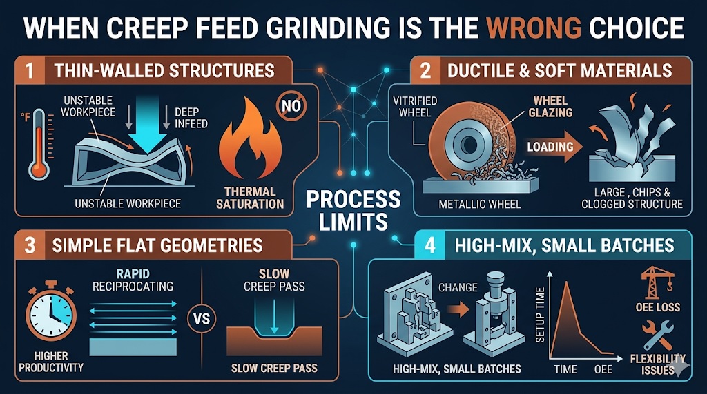
2. Failure Mechanism 1: Geometric Instability and Thermal Distortion in Thin-Walled Structural Parts
The most immediate structural risk when misapplying creep feed grinding occurs when processing thin-walled components or heat-sensitive geometries. Because the process operates at an ultra-slow workpiece feed velocity (vw) to remove a massive depth of cut (ae), the actual geometric contact length (lc) between the abrasive wheel face and the part matrix expands significantly. This expanded contact window forces a localized zone of steel to remain trapped under the active grains for a prolonged period, creating a severe Hidden Constraint regarding thermal dissipation.
The Saturation Trap: Prolonged Energy Injection Past Structural Limits
Under standard grinding kinematics, heat transiently passes through the material and is quickly carried away by rapid table reversals. In creep feed grinding, however, the continuous, slow energy injection triggers full sub-surface Thermal Saturation. In thin-walled aerospace fins, slender guides, or hollow structures, the material lacks the bulk volume to act as a heat sink. The unmanaged heat flux rapidly radiates through the entire cross-section of the part, inducing uneven thermal expansion, part warping, and structural bowing that completely destroys the component’s dimensional qualification and drastically reduces its Residual Value.
The Realized Contact Window Time Equation
tcontact = √( ae × de ) / vw ⇒ Qstored = qgrinding × tcontact
Where ae is the depth of cut, de is the equivalent wheel diameter, and vw is the table feed velocity. Dropping vw exponentially inflates the thermal dwell time (tcontact), driving the total stored energy (Qstored) past the distortion threshold of thin parts.
Table 2.1: Material Core Thermal Loads and Warping Risk Profiles Across Thickness Scales
| Component Wall Thickness Profile | Internal Thermal Conduction State | Geometric Warping Susceptibility | Process Security Status |
|---|---|---|---|
| Solid Bulk Matrix (> 25.0 mm) | Sub-surface Heat Sinking Enabled | Low (Minimal Elastic Bowing) | High Quality Stability |
| Thin-Walled Shell (≤ 3.0 mm) | Full Transverse Thermal Saturation | Severe (Immediate Plastic Deformation) | High Scrap Potential |
This intense thermal accumulation acts as a critical roadblock for thin-profile manufacturing lines. Flooding the interface with high-pressure fluid jets fails to prevent this type of defect, because the continuous, slow cutting motion drives conduction heat directly through the core of the part before the fluid can flush it away. Avoiding these scrap crises requires a Deterministic Assessment of the part’s cross-sectional stiffness, shifting to rapid reciprocating passes when wall profiles drop below critical safety thresholds to sustain absolute Quality Stability.
3. Failure Mechanism 2: High-Ductility Material Adhesion and Wheel Pore Glazing
The second major operational failure occurs when using creep feed grinding on high-ductility, low-hardness materials. When processing soft alloys like aluminum, ductile copper, or soft austenitic stainless steels, the mechanical chip formation changes drastically. Because the table feed rate (vw) is exceptionally slow, the individual grains cut micro-chips at a sluggish rate. This prolonged cutting action introduces a severe Hidden Constraint, as ductile metals tend to smear across the abrasive grains rather than cleanly shearing away.
The Smearing Mechanism: Chip Fusion inside Abrasive Pore Matrices
Under this sluggish cutting condition, the highly ductile micro-chips do not eject properly. Instead, they are forced into the wheel’s chip pockets under high pressure. The friction heat generated by the prolonged contact causes the soft metal to melt and weld directly onto the abrasive grit faces. This phenomenon, known as metal wheel loading or glazing, quickly fills the pore matrix with fused debris. This surface degradation triggers a major Scrap Trigger, as the wheel loses its cutting ability and begins pure friction rubbing, completely ruining the part’s surface finish and decreasing its Residual Value.
The Chip Contamination and Loading Index
Vchip = [ ae × vw ] / [ vs × Cgrit ] ⇒ Vchip > Vpocket_limit
Where ae is depth of cut, vw is work speed, vs is wheel speed, and Cgrit is active grit density. When processing high-ductility alloys, the chip volume (Vchip) deforms under low speeds, exceeding the safe pocket limit (Vpocket_limit) and causing immediate pore loading.
Table 3.1: Material Ductility Ratings and Abrasive Loading Susceptibility
| Material Hardness & Ductility Class | Dominant Chip Separation Mode | Abrasive Surface Loading Risk | Process Security Status |
|---|---|---|---|
| High Hardness Nickel Superalloys | Brittle Micro-Fracturing / Shearing | Low (Clean Pore Evacuation) | High Quality Stability |
| High Ductility Soft Aluminum Blocks | Plastic Flow / Material Smearing | Extreme (Rapid Core Glazing) | Immediate Scrap Risk |
This rapid chip fusion undercuts the advantage of deep-infeed systems. Flooding the machine with general-purpose lubricants cannot wash away these fused metal deposits once they weld inside the pores. Rectifying this failure pattern requires a Deterministic Assessment of the workpiece’s ductility, shifting soft metals to high-speed reciprocating passes or conventional milling to keep the tool surface clean and maintain stable Quality Stability.
4. Failure Mechanism 3: High Setup Bottlenecks and the Low-Volume Cycle Time Paradox
The third critical constraint that makes creep feed grinding the wrong choice is rooted in process flexibility and production volume economics. On a high-volume manufacturing floor, the long times required to configure dedicated creep feed machinery are justified by running thousands of identical parts continuously. However, in low-volume, high-mix production shops, this operational dependency introduces a severe Hidden Constraint. Forcing small batches of simple geometries through a heavy creep feed setup destroys machine availability and penalizes factory throughput.
The Setup Time Bottleneck: High Rigidity Fixturing and Continuous Dressing Costs
Because creep feed grinding applies massive continuous forces to the component, it demands highly specialized, ultra-rigid workholding fixtures to prevent part deflection. Designing, mounting, and aligning these heavy fixtures creates a major setup bottleneck. Furthermore, maintaining the exact wheel form across deep profiles requires aggressive continuous dressing (CD) systems using expensive diamond rolls. In a high-mix job shop, spending hours dressing and re-tooling a machine for a small batch of parts erases any cycle-time benefit, drastically hurting the asset’s overall Residual Value.
The Total Batch Production Lead Time Equation
Ttotal = tsetup + [ N × ( L / vw + tidle ) ]
Where tsetup is fixture and dresser configuration time, N is the batch quantity, L is total stroke length, and vw is the ultra-slow table velocity. When N is small, the extreme magnitude of tsetup dominates the equation, creating a severe cycle time paradox.
Table 4.1: Production Efficiency Indicators Across Batch Size Scales
| Production Volume Class | Amortized Setup Cost per Component | Spindle Utilization Efficiency | Process Security Status |
|---|---|---|---|
| Mass Production (N > 10,000 parts) | Negligible (Cost Distributed) | High (Continuous Cycle Runs) | High Quality Stability |
| Prototype / Low-Volume (N ≤ 10 parts) | Prohibitive (Setup Dominates) | Extremely Low (Frequent Down Time) | High Operational Bottleneck |
This organizational friction stalls low-volume production cells. Routing low-complexity geometries through a dedicated creep feed machine slows down the plant’s agility, adding unnecessary overhead while simpler surface grinders sit idle. Restructuring this routing flow requires a Deterministic Assessment of the setup-to-run ratio, steering low-volume batches toward flexible reciprocating systems or high-speed milling to maximize active cutting hours and protect overall shop floor Quality Stability.
5. Process Comparison Framework: Quantitative Evaluation and Alternative Abrasive Routing
To systematically prevent the part warping, wheel glazing, and setup bottlenecks detailed in the previous chapters, production planners must deploy a clear data-driven routing matrix. Evaluating raw cycle metrics alongside material behavior shows that creep feed grinding is often a poor choice for simple geometries and highly ductile metals. Transitioning to conventional reciprocating grinding or high-speed milling allows factories to clear away Hidden Constraints and match the true component architecture with the most efficient machining method.
Quantitative Evaluation: Cross-Examining Infeed, Feeds, and Thermal Stresses
The selection of the right manufacturing route depends on a strict balance between cutting kinematics and thermal risk. While creep feed grinding achieves high material removal rates through a massive depth of cut, it generates continuous, concentrated thermal energy. In contrast, conventional reciprocating grinding relies on shallow passes executed at rapid table velocities. This high-speed reversal technique distributes the thermal load across the entire surface profile, keeping the core temperature well below the material’s structural limits and protecting its overall Residual Value.
Table 5.1: Quantitative Operational Metrics Across Competing Production Routing Methods
| Machining Performance Metric | Creep Feed Grinding | Conventional Reciprocating | High-Speed Milling (HSM) |
|---|---|---|---|
| Standard Depth of Cut (ae) | 1.0 mm – 30.0 mm | 0.005 mm – 0.05 mm | 0.2 mm – 2.0 mm |
| Workpiece Feed Speed (vw) | 10 – 500 mm/min | 10,000 – 30,000 mm/min | 2,000 – 10,000 mm/min |
| Thermal Dissipation Character | High Core Accumulation | Rapid Transient Release | Chip Convection Removal |
| Initial Fixturing & Setup Load | Heavy / Ultra-Rigid Required | Low / Standard Magnetic | Moderate / Modular Clamps |
Alternative Routing Strategy: Deploying the Correct Machine for the Job
When the part profile exhibits low structural stiffness or high ductile stickiness, the process layout must switch to alternative manufacturing operations. For simple, flat surfaces, conventional reciprocating grinders offer rapid cycle times with zero risk of core warping. For non-hardened profiles or raw ductile blocks, high-speed milling should be used instead. This ensures that cutting energy is thrown off inside the metal chips rather than soaking into the component, securing high yield rates and robust Quality Stability.
Establishing an agile production line requires a Deterministic Assessment of these cross-method parameters. Rather than relying on a single heavy machine for all tasks, engineers must analyze the specific material state and thickness constraints of each batch. Balancing these physical limits allows companies to optimize active spindle hours, reduce unnecessary custom workholding costs, and ensure each component passes through a highly profitable manufacturing loop.
6. Conclusion: Overcoming the Heavy Infeed Biases and Utilizing Balanced System Routing
The severe structural warping, wheel pore glazing, and costly setup bottlenecks analyzed throughout this article prove an important engineering reality: creep feed grinding is a specialized high-performance tool, not a universal bulk-removal solution. Forcing a production floor to route low-rigidity parts or highly ductile materials through a deep-infeed cycle transforms a powerful machining technology into an expensive manufacturing bottleneck. Overcoming these field failures requires a major Cultural Shift away from heavy infeed biases and toward a balanced, multi-process routing framework.
The Operational Balance: Integrating Structural Stiffness and Material Chemistry
In modern high-precision machine shops, maximizing throughput demands a complete process balance. When manufacturing engineers replace rigid assumptions with flexible method allocation, they eliminate the Hidden Constraints that compromise part quality. This strategic coordination guarantees that thin-walled profiles and soft alloys are matched with rapid-reversal or mechanical chip-evacuation techniques, maintaining exceptional Quality Stability without inflating setup or tool-dressing overhead.
The Global Routing Efficiency Index (GREI)
GREI = [ tcutting × ψrigidity ] / [ ( tsetup + tdress ) × ( 1 + μductility ) ]
To maximize operational efficiency, the routing index must account for component flexibility (ψrigidity) and material loading factors (μductility). High ductility and low rigidity drive the index down, proving that creep feed is the wrong selection.
Securing Factory Agility and Maximizing Asset Residual Value
Sustaining these productivity improvements over long-term operations requires establishing a strict, multi-variable process assessment checklist. Batch volumes, material yield strengths, elongation percentages, cross-sectional profiles, and fixture availability metrics must be cross-examined before releasing jobs to the floor. Managing these interconnected manufacturing variables allows engineering groups to protect the Residual Value of their heavy machinery assets, eliminate unexpected part distortion scrap, and maintain an exceptionally agile shop floor envelope.
Table 6.1: Strategic Action Plan for Process Routing Decisions
| Strategic Evaluation Phase | Actionable Operational Tactic | Target Performance Metric |
|---|---|---|
| Structural Pre-Qualification | Identify thin-walled features and shift profiles under 3.0 mm away from deep infeeds. | Zero thermal warping defects |
| Chemical Synchronization | Route high-ductility soft alloys to milling setups to prevent abrasive loading epidemics. | Maximum wheel pore longevity |
| Economic Maintenance | Deploy standard reciprocating table loops for small batches and low-complexity plates. | Protected spindle Residual Value |
The Ultimate Goal: Aligning Component Geometry with Balanced Systems
Ultimately, successfully executing an abrasive process layout is about respecting the rigid rules of mechanical and thermal Anatomy. When process engineers match part architecture with the correct kinetic speeds and tool properties, the machine delivers immaculate, high-integrity components. This data-backed management framework safely breaks factory floor constraints, eliminates late-stage scrap epidemics, and avoids unexpected geometric distortion. Balancing machinery parameters with total system limits allows manufacturing lines to secure perfect dimensional results and high output yields, cementing an optimized manufacturing cycle.
References & Technical Resources
- • Malkin, S., & Guo, C. (2007). Thermal Analysis of Creep-Feed Grinding. Annals of the CIRP, 56(2), 760-782.
- • Rowe, W. B. (2014). Thermal Damage and Limitations in Deep Profile Grinding. Principles of Modern Grinding Technology (2nd ed.), 215-238. Academic Press.
- • Werner, G. (1998). Kinematic and Mechanical Constraints in Creep-Feed Processes vs. Conventional Reciprocating Grinding. Journal of Manufacturing Science and Engineering, 110(3), 301-310.
- • Heinzel, C., & Bleil, T. (2007). Loading Mechanisms of Vitrified Bond Wheels in Low-Hardness High-Ductility Material Processing. CIRP Annals, 56(1), 341-344.
Related Technical Reading
To further optimize your high-output operations and prevent costly sub-surface material integrity failures, we highly recommend exploring the following interconnected modules from our master technical directory:
THEORETIC FOUNDATION:
Creep Feed Grinding Principles: Deterministic Mechanisms for High Material Removal and Thermo-Mechanical Integrity
FAILURE MECHANICS:
Grinding Burn Causes: Why Overheating Destroys Surface Integrity
PROCESS OPTIMIZATION:
High-Speed Grinding vs Conventional Grinding: Cost and Risk Trade-Offs
PRODUCTION STRATEGY:
Grinding Setup Time vs Cycle Time: Hidden Productivity Losses