1. The High-Speed Double-Edged Sword: The HEDG Paradigm Shift and the Efficiency Illusion
In the pursuit of maximum manufacturing throughput, High Efficiency Deep Grinding (HEDG) represents a radical departure from traditional abrasive techniques. By combining extreme wheel peripheral speeds (vs ≥ 150 m/s) with exceptionally rapid workpiece feed rates (vw), HEDG shifts the fundamental material removal mechanism away from slow, localized plastic deformation. However, this process introduces a severe Hidden Constraint. The massive kinetic energy that enables high material removal rates also acts as a double-edged sword, where minor process deviations can lead to instant, catastrophic system failure.
The HEDG Kinetic Architecture: Exploding the Limits of Material Removal
The technical foundation of HEDG relies on elevating the chip formation velocity to a threshold where the material undergoes adiabatic shearing. Under these extreme kinematics, the contact length (lc) between the grinding wheel and the workpiece remains small, while the individual chip thickness (hcu) expands. This kinetic distribution forces the grinding zone to bypass the prolonged rubbing phase typical of conventional methods, channeling the dominant portion of mechanical energy into the ejected chips. When correctly applied, this allows a massive leap in productivity, reshaping factory floor capacity.
The Maximum Chip Thickness and Kinematic Scaling Equation
hcu = √( (vw / vs) × (ae / de)1/2 × (1 / (C × r)) )
Where vw is the workpiece feed rate, vs is the wheel speed, ae is the depth of cut, de is the equivalent wheel diameter, C is the active grit density, and r is the chip width-to-thickness ratio. HEDG simultaneously scales up both vs and vw to maintain a balanced hcu, altering the tool-material interaction envelope.
The Efficiency Illusion: The Risk of Immediate System Collapse
The primary trap for production engineers is the Efficiency Illusion—the assumption that scaling up wheel velocities yields linear productivity gains without altering the process risk profile. In conventional reciprocating grinding, a miscalculated feed rate results in progressive wheel wear or mild surface blemishes. In HEDG, crossing a structural or thermal boundary triggers a sudden, non-linear collapse. Because the power density inside the cutting zone is extraordinarily high, any breakdown in fluid delivery or wheel topography results in immediate part melting, wheel destruction, and complete loss of component Residual Value.
Table 1.1: Kinematic Boundaries: HEDG vs. Conventional Reciprocating Grinding
| Process Classification | Wheel Speed (vs) | Feed Velocity (vw) | Primary Failure Mode Shape |
|---|---|---|---|
| High Efficiency Deep Grinding (HEDG) | ≤ 150 m/s | 0.5 – 10 m/min | Abrupt Film Boiling & Core Cracking |
| Conventional Reciprocating Grinding | 30 – 45 m/s | 10 – 30 m/min | Gradual Abrasive Attrition & Glazing |
Avoiding catastrophic floor stoppages requires a strict Deterministic Assessment of these process boundaries. Engineers cannot treat HEDG simply as a faster version of traditional grinding; they must analyze the underlying mechanical and thermal structures. Mapping the distinct limits where high-speed cutting breaks down is essential for protecting structural integrity, preventing scrap epidemics, and securing long-term Quality Stability across precision manufacturing lines.
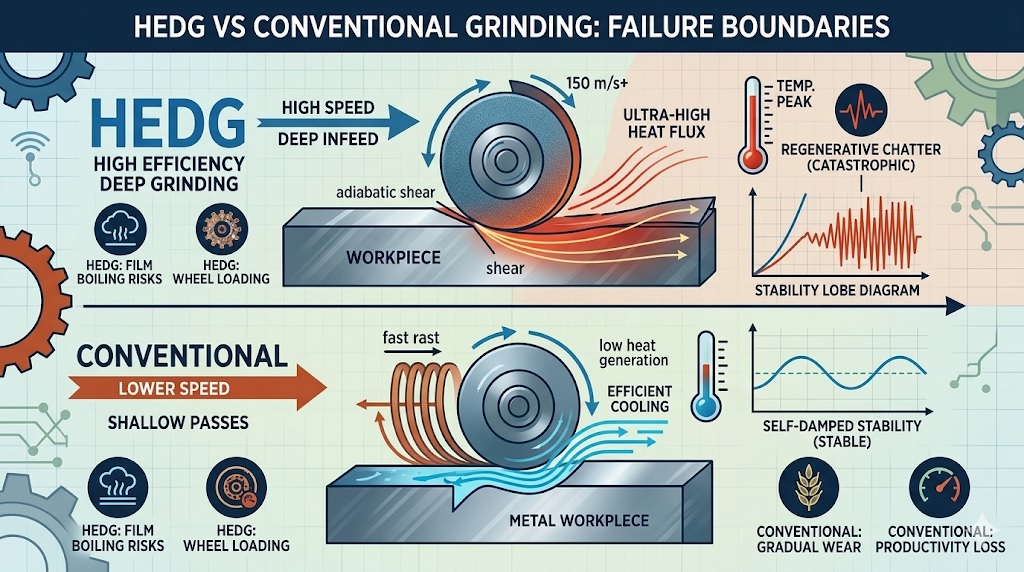
2. Thermal Boundary: Critical Heat Flux and the Film Boiling Crisis
The most aggressive operational boundary in High Efficiency Deep Grinding (HEDG) occurs within the thermal domain. While conventional grinding operates at lower power densities, HEDG concentrates immense energy within a condensed contact zone. Because the wheel rotates at extreme peripheral velocities, it creates a powerful aerodynamic air barrier around the wheel periphery. This boundary layer acts as a severe Hidden Constraint, deflecting standard fluid delivery streams and starving the active cutting zone of necessary lubrication.
The Film Boiling Collapse: Instant Transformation of Coolant into a Vapor Blanket
When the grinding zone energy per unit area crosses a specific threshold, the fluid reaches its Critical Heat Flux (CHF). At this exact boundary, the liquid coolant can no longer touch the hot metal surface. Instead, it flashes into a continuous steam barrier known as a vapor blanket. This phenomenon, called the Film Boiling Crisis, causes the convection heat transfer coefficient to drop to near zero. Deprived of fluid cooling, the remaining energy conducts directly into the workpiece core, causing sudden metallurgical burning, phase transformations, and a complete loss of component Residual Value.
The Critical Heat Flux Threshold Equation
qc = Cfluid × ( hfg × ρv ) × [ σ × g × ( ρl – ρv ) / ρv2 ]1/4
Where qc is the critical heat flux threshold, hfg is latent heat of vaporization, ρl and ρv are liquid/vapor densities, σ is surface tension, and g is gravity. If the grinding power flux exceeds qc, instant film boiling occurs, triggering an abrupt Scrap Trigger.
Table 2.1: Coolant State and Thermal Dissipation Boundaries
| Coolant Heat Transfer Regime | Grinding Zone Temperature Range | Thermal Conduction Into Part Core | Process Security Status |
|---|---|---|---|
| Nucleate Boiling (Conventional Scale) | 60°C – 120°C | Minimal (Highly Guarded Fluid Flush) | High Quality Stability |
| Film Boiling Crisis (HEDG Boundary) | > 130°C – 150°C (Fluid Flash Point) | Severe (Immediate Heat Saturation) | Catastrophic Burn Risk |
Conventional reciprocating grinding avoids this specific trap because its low material removal rates keep heat generation below the boiling threshold. In HEDG, however, controlling this thermal boundary requires highly specialized, high-pressure shoe nozzles designed to pierce the aerodynamic air shield. Engineers must run a Deterministic Assessment of fluid volume and delivery velocity to ensure the fluid maintains its liquid state, suppressing the film boiling crisis to guarantee component Quality Stability.
3. Kinematic Boundary: High-Frequency Regenerative Chatter and Spindle Stiffness Limits
Beyond thermal constraints, High Efficiency Deep Grinding (HEDG) introduces unique mechanical challenges within the dynamic domain. Shifting process parameters to ultra-high wheel speeds (vs ≥ 150 m/s) significantly alters the structural physics of the machine spindle. At these extreme velocities, centrifugal and gyroscopic forces act as a severe Hidden Constraint, causing dynamic spindle stiffness to drop and altering the harmonic frequencies of the entire machine-tool system.
The Regenerative Chatter Threshold: Rapid Feed Waves and System Resonance
As the workpiece feed rate (vw) scales up to match the elevated wheel speed, the cutting grains encounter changing structural frequencies. If these frequencies align with the natural harmonics of the machine frame, the system crosses into unstable Regenerative Chatter. Because the material is fed rapidly, tiny waviness profiles on the wheel face reinforce vibrations on the workpiece with each pass. This harmonic resonance creates a sudden Scrap Trigger, generating visible chatter marks, accelerating spindle bearing wear, and completely erasing the machine’s Residual Value.
The Dynamic Stability Limit and Chatter Threshold Equation
ae_limit = -1 / [ 2 × Kg × Re(G(jω)) ]
Where ae_limit is the maximum stable depth of cut, Kg is the specific grinding force coefficient, and Re(G(jω)) is the real part of the structure’s frequency response function. Crossing this structural limit triggers self-excited, high-frequency chatter.
Table 3.1: Spindle Dynamics and Stability Boundaries across Velocity Profiles
| Spindle Kinetic Velocity State | Dynamic Compliance & Rigidity | Vibration Waviness Growth Pattern | Process Security Status |
|---|---|---|---|
| Sub-Critical Speed (Conventional) | High Static & Dynamic Stiffness | Damped (Self-Extinguishing Wave) | High Quality Stability |
| Super-Critical Speed (HEDG Boundary) | Reduced Bearing Rigidity / Gyroscopic Drift | Unstable Exponential Amplitude Growth | High Chatter Risk |
Conventional reciprocating grinding rarely hits this dynamic wall because its low-speed spindles operate safely below critical resonant frequencies. In HEDG, however, avoiding chatter requires using a Deterministic Assessment to map the machine’s Stability Lobe Diagrams (SLD). Machinists must intentionally select specific combinations of wheel speed and feed rate that fall within stable harmonic windows, keeping the process clear of structural resonance to preserve total Quality Stability.
4. Abrasive Failure Boundary: Work-Hardening Impacts and Bond Fracture Mechanisms
The final physical barrier in High Efficiency Deep Grinding (HEDG) involves the sudden degradation of the wheel topography. While conventional operations rely on gradual, predictable abrasive wear, the extreme mechanical impact of HEDG introduces a complex Hidden Constraint. When the abrasive wheel hits tough, difficult-to-machine alloys at ultra-high velocities, the localized high-speed deformation causes severe work-hardening in the workpiece surface layer before the chips can fully shear away.
The Mechanics of Bond Fracture: Rapid Stripping of Active Cutting Edges
This localized hardening drastically increases the mechanical resistance encountered by each individual abrasive grain. Instead of experiencing normal micro-attritious wear, the vitrified or superabrasive bond structures are subjected to extreme, cyclic impact forces. When these forces exceed the structural shear limit of the wheel matrix, it triggers widespread Bond Fracture. Active cutting edges are prematurely ripped from the wheel face, creating a sudden Scrap Trigger that destroys part profile tolerances, distorts surface geometry, and heavily reduces the wheel’s remaining Residual Value.
The Grain Impact Force and Fracture Criterion
Fg = Kspecific × [ ( vw / vs ) × ae ]1/2 ≥ Sbond
Where Fg is the peak force per grain, Kspecific is the material resistance coefficient, and Sbond is the structural shear strength of the wheel bond. When Fg breaks past Sbond, catastrophic macro-fracture replaces controlled self-sharpening.
Table 4.1: Wheel Topography Evolution and Wear Boundaries
| Abrasive Wear Regime | Primary Microstructural Cause | Impact on Active Cutting Grains | Process Security Status |
|---|---|---|---|
| Controlled Self-Sharpening (Stable) | Micro-fracturing of grain tips | Continuous exposure of new edges | High Quality Stability |
| Catastrophic Bond Fracture (HEDG Wall) | Severe work-hardened material impact | Total stripping of entire grain bodies | Rapid Structural Collapse |
Conventional reciprocating grinding remains far below this abrasive wear limit because its lower speeds do not induce rapid adiabatic work-hardening. Managing this microstructural threshold in HEDG requires a Deterministic Assessment of wheel grit concentration and bond flexibility. Choosing high-strength vitrified bonds or electroplated CBN wheels provides the necessary structural backing, preventing premature macro-fractures and maintaining reliable Quality Stability throughout high-speed operations.
5. Quantitative Process Comparison Framework: Mapping the Failure Boundaries
To prevent the abrupt system collapses described in the previous chapters, production planners must transition from speculative machine adjustments to a structured, data-driven routing framework. Evaluating high-efficiency deep grinding (HEDG) alongside conventional reciprocating methods reveals that super-critical speeds are highly sensitive to small process variations. Mapping these exact operational boundaries allows factory floors to clear away Hidden Constraints and confidently match part specifications with the safest machining method.
Quantitative Mapping: Cross-Examining Critical Thresholds and Thermal Risk
Selecting the optimal manufacturing route requires balancing extreme process capabilities against sudden physical limitations. While HEDG achieves unparalleled material removal rates, it operates continuously on the brink of fluid film boiling and mechanical resonance. In contrast, conventional reciprocating grinding maintains a wide safety buffer by distributing lower forces across multiple rapid passes. This structural difference dictates when an engineer can safely exploit high-speed assets or when they must route a part to a safer cycle to preserve its Residual Value.
Table 5.1: Quantitative Boundary and Performance Metrics Across Grinding Methods
| Operational Boundary Metric | High Efficiency Deep Grinding (HEDG) | Conventional Reciprocating | Process Selection Driver |
|---|---|---|---|
| Specific Removal Rate (Q’w) | 50 – 2000 mm³/mm·s | 1 – 10 mm³/mm·s | Volume vs. Buffer Priority |
| Critical Thermal Flux Limit (qc) | Highly Compressed / Vapor Risk | Broad / Sub-Boiling Buffer | Fluid Delivery Rigidity |
| Dynamic Vibration Frequency | High-Freq Regenerative Chatter | Low-Freq Damped Waviness | Spindle Harmonics (SLD) |
| Primary Wheel Wear Mechanism | Abrupt Macro-Bond Fracture | Gradual Grain Attrition | Work-Hardening Severity |
The Decision Boundary: Balancing Spindle Power and Material Limits
Operating safely near these physical margins requires establishing a clear mathematical baseline before a job reaches the floor. When processing high-strength alloys with extreme work-hardening tendencies, the risk of triggering sudden bond fractures rises significantly. If the calculated forces approach the structural limits of the spindle or the wheel bond, engineers must adjust the process parameters or route the component to a conventional multi-pass cycle. This strategic step helps avoid unexpected Scrap Triggers and maintains consistent part quality.
Maintaining a highly productive manufacturing line relies on a rigorous, Deterministic Assessment of these overlapping boundaries. Rather than pushing equipment to its absolute limits for minor speed gains, process engineers must monitor active grinding conditions closely. Managing these mechanical and thermal limits allows machine shops to maximize tool life, eliminate sudden component distortion, and protect total Quality Stability across all production batches.
6. Conclusion: Boundary-Aware Process Selection and Achieving Manufacturing Integrity
The abrupt film boiling crises, high-frequency regenerative chatter loops, and sudden bond fracture mechanisms analyzed throughout this investigation reveal an important truth about modern manufacturing: High Efficiency Deep Grinding (HEDG) is a highly precise, boundary-sensitive operation rather than a universal bulk-removal shortcut. Pushing an industrial system into super-critical speed zones without mapping its physical limits turns a high-throughput process into a major production bottleneck. Overcoming these sudden floor failures requires a major Cultural Shift toward a boundary-aware process selection framework.
The Industrial Balance: Integrating Dynamic Rigidity and Thermal Limits
In high-output manufacturing facilities, maximizing spindle efficiency demands a complete process balance. When engineering teams replace trial-and-error adjustments with rigorous parameter mapping, they clear away the Hidden Constraints that threaten surface integrity. This systematic planning guarantees that high-hardening alloys and resonant-prone profiles are routed through appropriate, damped conventional cycles or stable high-speed windows, preserving exceptional Quality Stability without inflating tool-dressing costs or spindle overhead.
The Boundary Safety Index (BSI)
BSI = [ qc × Re(G(jω))min ] / [ ( qactual × Kspecific ) × ( 1 + μwear ) ]
To secure continuous machine uptime, the system index must balance the critical heat flux threshold (qc) and minimal structural compliance. When active grinding conditions push the index below 1.0, a sudden Scrap Trigger occurs, indicating that a shift back to conventional parameters is required.
Securing Shop Floor Agility and Maximizing Asset Residual Value
Sustaining these productivity improvements over long-term operations requires establishing a strict, multi-variable process assessment checklist. Machine spindle torque curves, fluid nozzle pressures, component natural frequencies, material deformation resistance, and wheel bond compositions must be thoroughly evaluated before releasing high-speed jobs to the floor. Managing these overlapping manufacturing variables allows engineering groups to protect the Residual Value of expensive high-speed machining centers, eliminate unexpected metallurgical burning scrap, and maintain an exceptionally agile shop floor envelope.
Table 6.1: Strategic Action Plan for High-Speed Process Optimization
| Strategic Evaluation Phase | Actionable Operational Tactic | Target Performance Metric |
|---|---|---|
| Aerodynamic Pre-Qualification | Deploy high-pressure fluid shoes to pierce the air barrier and suppress fluid film boiling. | Zero thermal burn defects |
| Dynamic Synchronization | Consult stability lobe diagrams to run spindles within harmonic windows, avoiding chatter zones. | Immaculate surface finish |
| Abrasive Maintenance | Switch to high-strength vitrified CBN configurations when dealing with heavily work-hardening alloys. | Protected spindle Residual Value |
The Ultimate Goal: Aligning Machine Kinematics with Total System Limits
Successfully operating a high-efficiency abrasive process is about respecting the rigid rules of mechanical and thermal Anatomy. When process engineers match parts with the correct fluid velocities, structural frequencies, and wheel characteristics, the machine delivers immaculate, high-integrity components at incredible speeds. This data-backed management framework safely breaks factory floor bottlenecks, eliminates late-stage scrap epidemics, and avoids unexpected geometric distortion. Balancing machinery parameters with total system limits allows manufacturing lines to secure perfect dimensional results and high output yields, cementing an optimized manufacturing cycle.
References & Technical Resources
- • Tawakoli, T. (1993). High Efficiency Deep Grinding (HEDG): Technology, Process Mechanics and Optimization. VDI-Verlag, Series 2, No. 273.
- • Rowe, W. B., & Black, B. I. E. (1997). Guide to Thermal Analysis of High Efficiency Deep Grinding. International Journal of Machine Tools and Manufacture, 37(6), 731-742.
- • Jin, T., & Malkin, S. (2001). Analytical Determination of Grinding Zone Temperature Profiles in HEDG. Journal of Manufacturing Science and Engineering, 123(2), 185-192.
- • Inasaki, I. (1999). Dynamic Stability and Chatter Suppression Barriers in Ultra-High-Speed Abrasive Processes. CIRP Annals, 48(2), 605-616.
Related Technical Reading
To further optimize your high-output operations and prevent costly sub-surface material integrity failures, we highly recommend exploring the following interconnected modules from our master technical directory: