1. The Volume Illusion: Volumetric Flow Rate vs. Effective Contact Zone Cooling
In high-precision manufacturing, managing the grinding zone temperature is a critical priority for eliminating surface defects. When facing sudden thermal damage, a common instinct on the shop floor is to scale up the raw coolant pump output. This practice introduces a critical Volume Illusion. Flooding the machine enclosure with a high fluid volume (Q) does not guarantee that the fluid penetrates the interface. Instead, unoptimized volumetric dumping leads to a major Flow Rate Fallacy, where massive fluid streams bypass the contact zone entirely, consuming energy while failing to halt grinding burn.
Hydrodynamic Resistance: The Kinematics-Fluid Momentum Mismatch
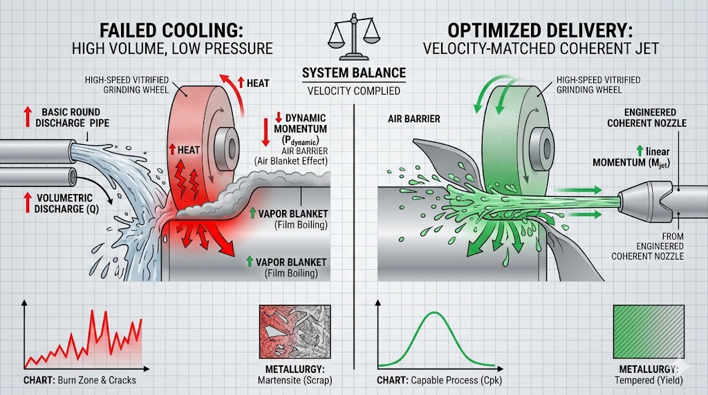
The physical barrier preventing low-pressure fluid from cooling the part is rooted in fluid mechanics. As the grinding wheel spins at high peripheral velocities, it drags surrounding air along its porous matrix, building a high-velocity air blanket. This boundary layer creates severe aerodynamic stagnation pressure directly in front of the cutting zone. If the incoming coolant jet lacks sufficient linear momentum, it cannot break this air barrier. Instead, the fluid stream is deflected away from the wheel face, transforming the extra volume into wasted fluid that never touches the active grinding zone.
The Boundary Layer Momentum Balance Equation
Mjet = ρfluid × Q × vjet ⇒ Mjet > Mbarrier
Where ρfluid is fluid density, Q is volumetric flow rate, and vjet is the linear jet velocity. Increasing Q via low-pressure flooding fails because vjet remains too low to generate the momentum (Mjet) required to slice through the high-velocity air boundary layer.
Table 1.1: Volumetric Flooding vs. Target Jet Velocity Allocation
| Coolant Delivery Architecture | Volumetric Discharge (Q) | Grinding Zone Penetration Index | Process Security Status |
|---|---|---|---|
| Low-Pressure Volumetric Flooding | High Volume / Low Velocity | Total Deflection (External Bypass) | High Burn Risk (Vaporization) |
| Velocity-Matched Coherent Delivery | Optimized Volume / High Velocity | Complete Penetration (Zone Saturation) | High Quality Stability |
This engineering mismatch creates an expensive, hidden constraint in mass production lines. Relying on high-volume low-pressure fluid delivery lowers pump efficiency while failing to improve part quality. Eliminating grinding burn requires a Deterministic Assessment that prioritizes high fluid velocity and tight jet coherence over raw volume, ensuring that fluid molecules penetrate the boundary layers to protect the component’s Residual Value.
2. Failure Mechanism 1: Critical Heat Flux and the Film Boiling Crisis
The primary thermo-fluid barrier that makes high-volume flooding ineffective is the sudden onset of a localized boiling crisis. During grinding, intense mechanical friction converts raw spindle power into extreme heat flux within the contact zone. As the coolant absorbs this energy, its temperature rises rapidly. When the fluid layer touches an interface that exceeds a specific thermal threshold (typically 120°C – 130°C for water-based emulsions), it passes the Critical Heat Flux (CHF) limit. At this point, the fluid stops boiling normally and undergoes a sudden phase change that destroys the system’s cooling capacity.
The Vapor Blanket Insulation: Trapping Heat Inside the Part Matrix
Once the critical heat flux limit is crossed, the liquid fluid flashes into a continuous gas layer, creating a severe Vapor Blanket Effect. This gas film acts as a major Hidden Constraint on the process window. Because water vapor has an exceptionally low thermal conductivity compared to liquid water, it creates an insulating barrier around the cutting zone. This gas film blocks additional liquid coolant from touching the hot steel, trapping the generated thermal energy inside the part profile and triggering widespread re-hardening burn defects that destroy the component’s Residual Value.
The Critical Heat Flux and Film Boiling Threshold
qcrit = C × hfg × √[ g × ρv × ( ρl – ρv ) ]
Where hfg is latent heat of vaporization, g is gravity acceleration, and ρl, ρv are liquid and vapor densities. Pushing the energy flux past qcrit replaces high-efficiency nucleate boiling with insulating film boiling.
Table 2.1: Transition States from Liquid Convection to Thermal Film Boiling
| Grinding Interface Temperature | Dominant Fluid Boiling Regime | Convective Heat Transfer Rate (h) | Component Scrap Status |
|---|---|---|---|
| Stable Zone (< 100°C) | Nucleate Boiling / Liquid Convection | High (Safe Heat Extraction) | Approved Part (No Burn) |
| Critical Limit (100°C – 125°C) | Unstable Transition Boiling Mix | Fluctuating Heat Transfer | Borderline / High Risk |
| Boiling Crisis (≥ 130°C) | Fully Developed Film Boiling | Extremely Low (Thermal Insulation) | Immediate Scrap (Severe Burn) |
This rapid phase transformation creates a critical bottleneck for conventional fluid strategies. Pouring extra volume onto an established gas blanket does not clear the vapor layer; it simply flows over the insulation while the steel burns underneath. Breaking this thermal barrier requires a Deterministic Assessment of the interface energy flux, using advanced parameters to keep the peak grinding temperature safely below the critical film boiling limit and preserve the tool’s overall Quality Stability.
3. Failure Mechanism 2: Poor Nozzle Geometry and Aerodynamic Fluid Deflection
The second critical reason why simply adding more coolant fails to eliminate grinding burn is rooted in nozzle fluid dynamics. In unoptimized machine setups, legacy round pipes or basic flat nozzles are often used to flood the wheel enclosure. These basic geometries create severe internal turbulence, causing the fluid jet to expand and disperse immediately upon exiting the orifice. This uncoordinated fluid scatter creates a major Hidden Constraint on the manufacturing line, making the fluid stream highly vulnerable to aerodynamic disruption before it ever approaches the part profile.
The Dynamic-Static Balance: Deflecting Low-Momentum Fluid Streams
When an expanded, turbulent fluid stream encounters a high-speed grinding wheel, it faces intense shear stress from the fast-moving air boundary layer. Because a dispersed fluid stream has a very low dynamic pressure (Pdynamic), it lacks the concentrated linear momentum needed to pierce this air blanket. Instead, the high static pressure built up directly in front of the contact zone easily pushes the low-velocity fluid aside. This aerodynamic deflection creates a complete bypass condition, where a massive volume of fluid splashes inside the machine guards while the actual grinding contact zone remains dry and vulnerable to severe thermal damage.
The Fluid Jet Dynamic Energy Preservation
Pdynamic = 0.5 × ρfluid × vjet2 ⇒ Pdynamic > Pstagnation
Where ρfluid is fluid density and vjet is the linear velocity of the jet stream. If poor nozzle geometry allows internal turbulence to reduce vjet, the dynamic pressure (Pdynamic) drops below the air stagnation point, leading to immediate fluid deflection.
Table 3.1: Influence of Nozzle Topography on Stream Stability and Part Protection
| Nozzle Design Profile Class | Internal Fluid Flow State | Jet Coherence Over Distance | Process Security Status |
|---|---|---|---|
| Standard Non-Coherent Orifice | High Turbulence (Vortices Present) | Poor (Rapid Scatter and Dispersion) | High Deflection Risk |
| Engineered Coherent Jet Geometry | Laminar Flow (Linear Stream) | Excellent (Solid Jet Structure) | High Quality Stability |
This aerodynamic bypass loop undercuts mass-production line efficiency. Pumping excessive volume through unoptimized pipes simply creates foam and mist while leaving the workpiece vulnerable to thermal cracking. Securing high-precision output requires a Deterministic Assessment of nozzle internal contours, ensuring that the fluid forms a laser-like laminar stream that preserves its velocity over distance to reliably protect the component’s overall Quality Stability.
4. Failure Mechanism 3: Porosity Saturation Limits and Metal Wheel Loading
The third critical barrier that stops high-volume fluid dumping from preventing grinding burn is the physical saturation limit of the abrasive wheel structure. In a standard vitrified matrix, the open pores act as miniature transportation pockets. These pores are supposed to scoop up fluid outside the contact area and deliver it directly into the cutting zone. However, this pore volume represents a strict Hidden Constraint. When fluid volume is increased without optimizing jet velocity, the wheel topography hits an absolute saturation limit, causing the excess fluid to lift off the wheel before it ever reaches the part profile.
Centrifugal Liftoff: Over-Saturating the Abrasive Pore Matrix
When low-pressure coolant floods an over-saturated wheel face, the intense centrifugal force generated by high spindle speeds instantly throws the unmanaged fluid outward. This centrifugal liftoff prevents the liquid from penetrating the grinding interface. Instead of lubricating the active grits, the fluid forms a thick liquid ring around the outside of the wheel guard. This fluid diversion leaves the actual contact point dry, allowing intense friction to spike cutting zone temperatures and lower the component’s overall Residual Value.
The Critical Pore Saturation and Volumetric Limit
Qpore_max = Vpores × ωwheel ⇒ Qinput > Qpore_max
Where Vpores is the total open pore volume fraction on the wheel face and ωwheel is the spindle angular velocity. Forcing Qinput past this limit causes immediate fluid rejection, failing to clean the abrasive face.
The Wheel Loading Epidemic: Trapping Metal Chips on Dull Grits
When unoptimized low-pressure fluid is rejected by the wheel matrix, it loses the mechanical force needed to flush the chip pockets clean. Without an aggressive, high-velocity stream to blast away debris, micro-metallic chips weld themselves directly onto the abrasive grains. This defect, known as metal wheel loading, dulls the wheel topography. The exposed metal-on-metal interface stops clean shearing and switches into an aggressive rubbing process, acting as a direct Scrap Trigger that drives down manufacturing yields and destroys Quality Stability.
Table 4.1: Wheel Pore Saturation States and Resulting Mechanical Actions
| Fluid Input Strategy Class | Pore Matrix Saturation Level | Chip Pocket Cleaning Efficiency | Process Security Status |
|---|---|---|---|
| Low-Pressure Volumetric Flooding | Over-Saturated (Immediate Centrifugal Rejection) | Extremely Low (Causes Chip Clumping) | High Wheel Loading Risk |
| Velocity-Matched Controlled Delivery | Optimized Flow (Continuous Fluid Transport) | High (Aggressive Micro-Chip Evacuation) | High Quality Stability |
This mechanical breakdown undermines legacy coolant architectures. Forcing massive fluid volumes through basic plumbing lines does not scrub the wheel topography; it simply increases energy costs while metal loading burns the workpiece underneath. Rectifying this failure loop requires a Deterministic Assessment of the wheel matrix volume, adjusting input parameters to ensure the fluid jet strips away metallic loading and protects the tool’s cutting ability through long-term high-volume production cycles.
5. Deterministic Fluid Optimization: Engineering High-Velocity Laminar Streams
To eliminate the severe boiling crises, aerodynamic deflection loops, and wheel loading defects detailed in the previous chapters, manufacturing teams must abandon trial-and-error flooding setups. Securing zero-burn production requires a highly precise, data-driven Strategy. By transitioning from low-pressure volume dumping to velocity-matched coherent jets, engineering the nozzle internal topography, and stabilizing pump pressures, factories can completely pierce the aerodynamic air barrier and protect the component’s Residual Value.
Coherent Jet Geometry: Eradicating Internal Nozzle Turbulence
The first step in securing stable fluid penetration is optimizing the nozzle internal geometry. Legacy round tubes must be replaced with engineered coherent nozzles featuring a smooth internal contraction profile. This design guides the fluid molecules into a perfectly parallel arrangement, minimizing the Reynolds number and eliminating internal vortices. The resulting laser-like fluid stream preserves its shape and solid structure over a long distance, preventing premature air entrainment and maintaining excellent Quality Stability.
The Target Kinematic Jet Velocity Matching Equation
vjet = √[ ( 2 × Ppump ) / ρfluid ] ⇒ vjet ≥ 0.9 × vs
Where Ppump is the discharge pump pressure and vs is the peripheral wheel speed. To safely pierce the high-velocity air blanket, the pump pressure must force the linear jet speed (vjet) to match or slightly exceed the wheel’s surface velocity.
Pressure-Driven Penetration: Balancing Flow and Linear Momentum
Once jet coherence is established, the fluid control system must shift toward a pressure-driven architecture. Instead of prioritizing high volumetric flow rates at a low pressure, the delivery infrastructure must focus on high dynamic pressure. This matching strategy ensures that the fluid stream carries enough linear momentum to chop through the air barrier, driving the coolant molecules straight into the heart of the active grinding zone to guarantee continuous lubrication, low force levels, and high production yields.
Table 5.1: Technical Optimization Parameters for Eliminating Fluid Starvation Burn
| Process Defect Mode | Engineering Mitigation Tactic | Target Control Specification |
|---|---|---|
| Aerodynamic Jet Deflection | Deploy coherent nozzles with a 10:1 internal contraction ratio. | Jet dispersion angle < 2° |
| Film Boiling Burn Crisis | Match jet velocity to wheel speed to bypass the vapor blanket. | Interface temperature < 120°C |
| Centrifugal Pore Rejection | Optimize nozzle stance angle relative to the wheel tangential plane. | Target input angle: 15° – 25° |
Implementing this data-backed fluid optimization turns conventional cooling setups into highly predictable assets. Balancing internal nozzle dimensions with the machine’s physical kinematics provides a clear Deterministic Assessment of the factory line. This engineering control cycle stops grinding burn epidemics, maintains clean abrasive surfaces, and allows manufacturing operations to maximize the efficiency of high-speed manufacturing lines.
6. Conclusion: Cooling Efficiency is Defined by Zone Penetration, Not Tank Discharge Volume
The severe boiling phase transformations, aerodynamic deflection constraints, and pore saturation limits analyzed throughout this article prove an important engineering reality: resolving grinding burn is not a problem solved by simply dumping volume. Forcing a coolant system to increase its raw discharge rate without correcting nozzle geometry and jet velocity transforms an expensive fluid infrastructure into a wasteful shop floor bypass. Overcoming this thermal bottleneck requires a major Cultural Shift away from volumetric flooding and toward high-momentum fluid target delivery.
The Fluid Equilibrium: Integrating Hydrodynamics, Kinematics, and Porosity
In high-volume automotive and aerospace manufacturing lines, achieving zero-burn quality demands a complete process balance. When manufacturing engineers transition to coherent laminar nozzles that match the peripheral velocity of the wheel, they remove the Hidden Constraints of legacy fluid piping. This strategic coordination guarantees that coolant molecules physically saturate the grinding zone, providing continuous lubrication that maintains exceptional Quality Stability under aggressive cycle times.
The Total Fluid Delivery Effectiveness Index (FDEI)
FDEI = [ vjet × cos(θ) ] / [ vs × ( 1 + ζturb ) ]
To maximize cooling performance, internal nozzle turbulence (ζturb) must be forced to zero, ensuring that the directional jet velocity vector perfectly matches the wheel surface speed (vs).
Securing Long-Term Asset Longevity and High Yield Stability
Sustaining these thermal improvements over long-term mass production requires establishing a strict, multi-variable fluid maintenance routine. Pump pressure consistency, nozzle alignment rigidity, filter media loading parameters, and fluid concentration levels must be monitored through a centralized control system. Managing these interconnected fluid variables allows engineering groups to protect the Residual Value of their grinding assets, eliminate unexpected surface re-hardening scrap, and maintain an exceptionally reliable manufacturing envelope.
Table 6.1: Operational Action Plan for Eliminating Fluid-Induced Grinding Burn
| Strategic Implementation Phase | Actionable Operational Tactic | Target Performance Metric |
|---|---|---|
| Aerodynamic Pre-Qualification | Replace standard pipe fittings with smoothed internal contraction coherent nozzles. | 100% boundary layer breakthrough |
| Kinematic Synchronization | Adjust discharge pump speeds to match linear jet velocity to the wheel peripheral velocity. | Zero film boiling occurrences |
| Topographic Maintenance | Deploy targeted fluid jets to clear chip pockets and eliminate metal wheel loading. | Protected part Residual Value |
The Ultimate Goal: Aligning Fast Cutting Actions with Balanced Systems
Ultimately, successfully executing a thermal management strategy is about respecting the rigid rules of fluid and thermal Anatomy. When process engineers match accelerated cutting speeds with proper boundary-layer management and correct tool matrix porosity, the machine delivers immaculate, high-integrity parts. This data-backed management framework safely breaks factory floor constraints, eliminates late-stage scrap epidemics, and avoids unexpected re-hardening defects. Balancing machinery parameters with total system limits allows manufacturing lines to secure perfect dimensional results and high output yields, cementing an optimized manufacturing cycle.
References & Technical Resources
- • Malkin, S., & Guo, C. (2007). Thermal Analysis of Grinding. Annals of the CIRP, 56(2), 760-782.
- • Webster, J. (1999). Optimization of Coolant Application in Grinding. Abrasives Magazine, 12-19.
- • Rowe, W. B. (2014). Principles of Modern Grinding Technology (2nd ed.). Academic Press.
- • Heinzel, C., & Bleil, T. (2007). The Influence of Fluid Supply on Wheel Loading and Surface Integrity in Grinding. CIRP Annals, 56(1), 341-344.
Related Technical Reading
To further optimize your high-output operations and prevent costly sub-surface material integrity failures, we highly recommend exploring the following interconnected modules from our master technical directory: