1. Introduction: The Brain of the Grinding Process
In the sophisticated ecosystem of high-precision manufacturing, the CNC Control System is far more than a simple executor of programmed paths; it is the cognitive center that synchronizes complex mechanical variables into a deterministic outcome. While milling and turning centers focus primarily on tool-tip trajectories, a grinding-specific CNC must manage a dynamic environment where the cutting tool—the grinding wheel—is constantly changing in size, topography, and cutting ability. The transition from manual “feel-based” grinding to autonomous sub-micron production is driven entirely by the evolution of these Advanced Control Functions.
The Complexity of Grinding Kinematics
Grinding is inherently a stochastic process involving millions of undefined cutting edges. Unlike a single-point turning tool, the interaction between the abrasive grains and the workpiece involves elastic deformation, plowing, and micro-shearing. A standard CNC controller lacks the computational overhead to manage these Grinding Dynamics. Dedicated grinding controls must integrate real-time algorithms for Wheel Dressing Synchronization, Thermal Compensation, and Force-Adaptive Control. Without these specific functions, the machine cannot maintain Quality Stability over a production batch, as the physical state of the wheel drifts from the first part to the last.
From Open-Loop to Closed-Loop Determinism
The primary value of modern CNC functions lies in their ability to close the loop between the virtual program and the physical reality of the machine bed. In high-end grinding, this is achieved through In-Process Feedback Mechanisms. The controller does not merely “hope” the part reaches the correct size; it utilizes high-speed interfaces to communicate with laser micrometers or acoustic emission sensors. This level of Dimensional Accuracy is only possible when the CNC software can process sensor data at the microsecond level and adjust the servo-loop commands instantaneously.
Etotal = ∫ [f(Vs, Vw, ae) + Δthermal + Δwear] dt
Equation 1.1: The Integral Control Logic for Managing Cumulative Process Drift in Grinding
Defining the Critical Control Modules
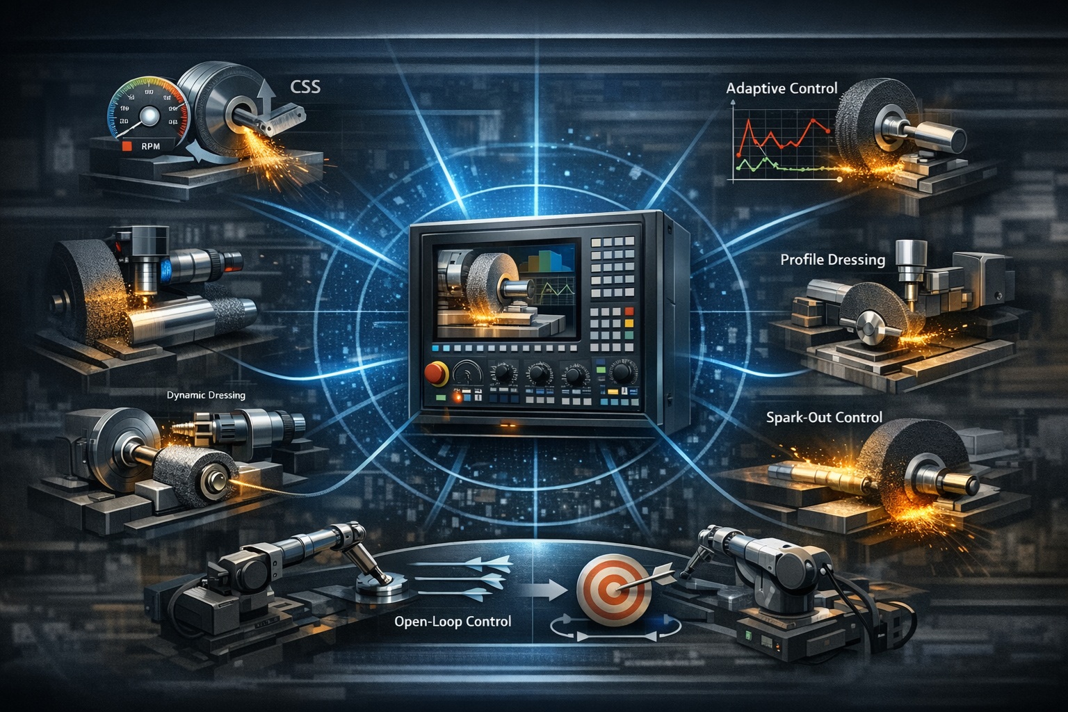
To master the grinding process, an engineer must understand the specific CNC Algorithms that govern different stages of the cycle. These include Gap Elimination to minimize non-productive air-cutting time, Constant Surface Speed (CSS) to maintain uniform cutting forces, and Spark-out Control to eliminate the residual spring-back of the machine-tool-workpiece system. Each of these functions acts as a pillar of Surface Integrity, preventing thermal damage and ensuring that the final surface finish (Ra) meets the stringent requirements of aerospace and medical industries.
In the following chapters, we will perform a deep-dive into each of these essential CNC functions. We will analyze the underlying mathematical logic, the hardware requirements for implementation, and the quantitative impact they have on Total Manufacturing Cost and Process Reliability. By the end of this analysis, the role of the CNC as the “Brain” of the grinding machine will be clearly established as the deciding factor in modern high-precision manufacturing.
| CNC Function Category | Technical Core Mechanism | Operational Outcome |
|---|---|---|
| Geometric Compensation | Real-time wheel diameter & profile tracking. | Maintenance of sub-micron Dimensional Accuracy. |
| Kinematic Control | CSS (Constant Surface Speed) & Feed Modulation. | Uniform Surface Integrity & prevented wheel loading. |
| Adaptive Feedback | Acoustic Emission & Spindle Load monitoring. | Optimized Cycle Time & minimized “Air-Cut” (Gap Elimination). |
| Synchronization | Integrated Dressing & In-Process Gauging. | Continuous Quality Stability across large batches. |
2. Constant Surface Speed (CSS) and Wheel Wear Compensation
In the world of precision grinding, the Cutting Velocity (Vs) is the most influential variable affecting both Surface Integrity and the Grinding Power consumption. Unlike a lathe tool, a grinding wheel’s diameter is in a state of constant reduction due to both natural grain shedding and intentional dressing cycles. Without a sophisticated Constant Surface Speed (CSS) function, the peripheral speed of the wheel would drop as its diameter decreases, leading to increased cutting forces, higher thermal loads, and inconsistent surface finishes.
The Physics of CSS: Maintaining Uniform Energy Input
The CNC’s CSS algorithm performs real-time calculations to adjust the Spindle RPM (n) based on the current Wheel Diameter (Ds). As the wheel wears from 400mm to 350mm, the rotational speed must increase proportionally to maintain a fixed surface speed (e.g., 35 m/s). This ensures that the Specific Grinding Energy—the energy required to remove a unit volume of material—remains constant. If Vs were allowed to drop, each abrasive grain would be forced to take a larger “chip thickness,” leading to premature wheel breakdown and potential “burning” of the workpiece surface.
Vs = (π × Ds × n) / 60,000
Equation 2.1: Relationship between Surface Speed (m/s), Diameter (mm), and RPM
Automated Wheel Wear and Dressing Compensation
Every time a Dressing Cycle is performed, the CNC must update its internal coordinate system. Modern Wheel Wear Compensation functions go beyond simple offset changes; they utilize a Dynamic Tool Model. When a diamond dresser removes 0.02mm from the wheel’s radius, the CNC’s Geometry Engine must instantaneously re-calculate the “Center of Tool” (COT) relative to the workpiece datum. Failure to synchronize this precisely results in a “Step Error” on the workpiece, where the post-dressed cut does not align with the pre-dressed surface, compromising Dimensional Accuracy.
Kinematic Precision and Quality Stability
The implementation of advanced CSS and wear compensation directly impacts the Total Manufacturing Cost. By maintaining a constant Vs, the wheel operates in its optimal “Self-Sharpening” zone for a longer duration, reducing the frequency of dressing and extending the Life-cycle of expensive CBN or Vitrified wheels. Furthermore, these functions eliminate the “morning drift” often seen in manual operations, where the machine’s thermal state and wheel condition change over time. The result is a process characterized by high Process Reliability and Quality Stability across thousands of cycles.
| Control Variable | CNC Response Mechanism | Precision Benefit |
|---|---|---|
| Diameter Reduction | Inverse proportional RPM increase via CSS algorithm. | Uniform chip thickness and Ra (Roughness). |
| Dressing Amount | Real-time update of G54-G59 work offsets. | Zero-drift Dimensional Accuracy post-dressing. |
| Thermal Expansion | Dynamic compensation based on Spindle RTD sensors. | Maintenance of sub-micron tool-tip position. |
| Wheel Profile | 3D path compensation for contoured wheels. | Perfect Geometric Fidelity in form grinding. |
3. In-Process Gauging and Adaptive Control
To achieve sub-micron Dimensional Accuracy in a high-volume production environment, relying on post-process inspection is often insufficient. In-Process Gauging acts as the “sensory nerves” of the CNC, providing real-time dimensional feedback during the actual grinding cycle. By integrating electronic touch probes or laser micrometers directly into the control loop, the CNC can transition from a programmed path-follower to an intelligent decision-maker that terminates the cycle only when the physical target is met.
Real-Time Dimensional Feedback Loops
The technical core of in-process gauging is the High-Speed Interrupt Logic within the CNC. As the grinding wheel approaches the final dimension, the gauge—typically a two-finger contact system or a non-contact pneumatic sensor—monitors the workpiece diameter at thousands of samples per second. When the measured value reaches the pre-defined “Pre-size” threshold, the CNC instantaneously switches from coarse feed to a specialized Fine-Feed Micro-step. This eliminates the risk of overshooting the tolerance due to mechanical lag or tool deflection.
Adaptive Control: Optimizing Infeed via Spindle Load
Adaptive Control (AC) functions take automation a step further by modulating the Infeed Rate based on real-time Spindle Load or acoustic emission signals. In many grinding applications, the workpiece geometry or material hardness may vary slightly. Instead of a fixed, conservative feed rate, the CNC’s AC algorithm maintains the maximum safe grinding force. If the wheel becomes glazed and the power consumption spikes, the CNC automatically reduces the feed to prevent thermal damage, ensuring consistent Surface Integrity while minimizing cycle time.
Fc ∝ ae × vf / vs → vf,adaptive = f(Plimit)
Equation 3.1: Adaptive Feed Rate Modulation (F: Force, a: Infeed, v: Speed, P: Power Limit)
Eliminating the Stochastic Nature of Grinding
By closing the feedback loop, these CNC functions effectively eliminate the stochastic variables inherent in abrasive machining. Process Reliability is greatly enhanced because the system compensates for the inevitable drifts in thermal state, wheel topography, and material inconsistency. For critical components in the aerospace and automotive sectors, this means a Zero-Defect production capability where every part is measured and validated *during* its creation, rather than after the fact.
| Control Module | Sensor Integration | Quality/Efficiency Impact |
|---|---|---|
| In-Process Gauge | Tactile Probes / Laser Scanning. | Strict Dimensional Accuracy (sub-micron). |
| Power Monitor | Current Transformers on Spindle Motor. | Prevention of Grinding Burn and Cracks. |
| Adaptive Feed | Real-time CNC Loop processing. | Reduction in Cycle Time by up to 25%. |
| Auto-Correction | Closed-loop offset adjustment. | Long-term Quality Stability in lights-out manufacturing. |
4. Advanced Dressing Synchronization Functions
The most critical differentiator between a standard CNC and a specialized grinding controller is the ability to manage Dressing Synchronization. Since the grinding wheel is a consumable tool that loses its “sharpness” and “form” during the process, the CNC must be capable of interrupting the machining cycle to perform dressing without losing the absolute coordinate reference. Advanced synchronization functions ensure that the transition between grinding and dressing is seamless, maintaining Quality Stability even in the most demanding high-production environments.
Continuous Dressing (CD) and Real-Time Compensation
For difficult-to-machine materials like nickel-based superalloys or hardened tool steels, Continuous Dressing (CD) is an essential CNC function. In this mode, the dressing tool (typically a diamond roller) remains in contact with the wheel *during* the actual grinding pass. This requires the CNC to perform a dual-axis interpolation: one for the grinding feed and a simultaneous, superimposed feed for the dresser. The controller must calculate the Wheel Erosion Rate in real-time and adjust the Z-axis or X-axis position to compensate for the shrinking wheel diameter, ensuring that the Dimensional Accuracy of the workpiece is not compromised by the dressing action.
Profile and Path Compensation Algorithms
When grinding complex contours or gear profiles, the wheel itself must be dressed into a specific Geometric Fidelity. Advanced CNCs utilize Profile Compensation macros that calculate the contact point of the dresser relative to the wheel’s normal vector. If the dresser wears down or the wheel’s curvature changes, the CNC’s Sub-program (Macro) automatically adjusts the tool path. This prevents “form error” where the radius or angle of the ground part drifts over time. Without this level of synchronization, Surface Integrity would fail due to the inconsistent topography of the abrasive surface.
Vdressing_ratio = (vdresser / vwheel) → f(vf, ad)
Equation 4.1: Synchronization Logic for Dressing Ratio and Infeed Compensation
Impact on Total Manufacturing Cost
The precision of these synchronization functions directly influences the Total Manufacturing Cost by optimizing the Life-cycle of both the grinding wheel and the diamond dresser. By performing “Just-in-Time” dressing—calculating exactly when the wheel topography has degraded—the CNC avoids over-dressing, which wastes expensive abrasive material. Furthermore, integrated In-Cycle Dressing reduces non-productive downtime, significantly increasing the throughput of the machine and ensuring a deterministic Process Reliability that is vital for automotive and medical component manufacturing.
| Synchronization Type | CNC Control Logic | Precision Outcome |
|---|---|---|
| Intermittent Dressing | Automatic cycle interrupt with G-code resume logic. | Consistency in Ra and profile accuracy. |
| Continuous Dressing | Simultaneous dual-path interpolation (Wheel/Dresser). | Zero thermal damage in heavy material removal. |
| Profile Remapping | Dynamic update of wheel profile data points. | Geometric Fidelity in complex form grinding. |
| Dressing Ratio Ctrl | Variable speed control of dresser vs. wheel RPM. | Optimized abrasive grain protrusion for peak cutting. |
5. Gap Elimination and Spark-out Control
Efficiency in grinding is often lost not during the cut, but in the approach. Gap Elimination and Spark-out Control are two CNC functions that target the opposite ends of the grinding cycle. While Gap Elimination minimizes the “Air-Cut” time to boost productivity, Spark-out Control manages the microscopic interaction between the wheel and workpiece to ensure Surface Integrity. Together, they provide a balanced approach to high-throughput, high-precision manufacturing.
Gap Elimination: Minimizing Non-Productive Time
In a typical cycle, the grinding wheel must approach the workpiece from a safe distance. Without Gap Elimination, the machine moves at a slow, conservative feed rate through the air to prevent a catastrophic crash. Modern CNCs utilize Acoustic Emission (AE) Sensors or high-sensitivity spindle load monitoring to detect the exact micro-second the wheel touches the workpiece. Upon detection, the CNC instantaneously switches from a rapid “Gap” feed to the actual “Grinding” feed. This reduction in air-cutting time can improve Total Manufacturing Cost by decreasing cycle times by as much as 15% to 30%.
Spark-out Control: Achieving Geometric Perfection
At the end of the infeed movement, the machine-tool-workpiece system retains stored elastic energy, causing a “spring-back” effect. Spark-out Control allows the wheel to continue traversing or dwelling without further infeed. This allows the cutting forces to decay to near-zero as the wheel removes the final microscopic layers of material deflected by the initial force. The CNC manages the number of spark-out passes or the duration of the dwell time based on the desired Dimensional Accuracy and Ra (Roughness). A well-executed spark-out is the final step in ensuring Quality Stability.
Ft(t) = F0 × e-t/τ (Where τ = Time Constant of the System)
Equation 5.1: Force Decay During Spark-out Phase (Exponential Decay Model)
The Synergy of Rapid Approach and Precision Finish
The integration of these two functions transforms the grinding cycle into a highly optimized Process Reliability model. Gap elimination handles the macro-movement with speed and safety, while Spark-out handles the micro-movement with finesse. For industries such as fuel injection or bearing manufacturing, where millions of parts are produced annually, the combined seconds saved and the micron-level consistency gained through these CNC functions are the primary drivers of Competitive Productivity.
| Cycle Phase | CNC Control Logic | Operational Benefit |
|---|---|---|
| Approach | AE-Sensor based Gap Elimination. | Elimination of Air-Cut; significant cycle time reduction. |
| Roughing | Power-Adaptive Feed rate modulation. | Maximized material removal without thermal damage. |
| Finishing | In-process gauging to final dimension. | Sub-micron Dimensional Accuracy. |
| Spark-out | Force decay cycles (dwell or strokes). | Perfect Surface Integrity and geometric correction. |
6. Conclusion: The Synergy of Hardware and Software
As we have analyzed through the preceding chapters, the performance of a modern grinding machine is no longer defined solely by its mechanical rigidity or the quality of its spindle. The CNC Control Functions we have discussed—from CSS and dressing synchronization to adaptive feed and spark-out control—represent the intelligence that translates physical potential into Dimensional Accuracy and Surface Integrity. In the sub-micron realm, the synergy between high-damping hardware and deterministic software is the only path to Quality Stability.
The Role of CNC as a Quality Guardian
Each control function acts as a safeguard against the inherent instabilities of the abrasive process. By closing the loop with In-Process Gauging and Gap Elimination, the CNC removes the reliance on operator intuition, replacing it with data-driven precision. This shift is fundamental for Process Reliability, allowing manufacturers to achieve high-volume throughput without sacrificing the microscopic tolerances required by the aerospace, medical, and automotive sectors. The CNC is effectively the guardian of the Total Manufacturing Cost, minimizing scrap and optimizing tool life-cycles.
Future Horizons: AI, Digital Twins, and Autonomous Grinding
The next evolution of grinding control lies in Autonomous Diagnostics and AI-Driven Optimization. Future CNC systems will utilize Digital Twins to simulate the thermal and mechanical behavior of the machine before a single grain touches the metal. Machine learning algorithms will analyze acoustic emission patterns to predict wheel glazing or dressing requirements with 99% accuracy. These “Self-Healing” processes will automatically adjust Adaptive Control parameters in real-time, ensuring that Geometric Fidelity is maintained even as environmental conditions shift, marking the beginning of the truly lights-out grinding factory.
Mastering the Digital Pulse of Precision
“Precision is no longer just a mechanical attribute; it is a computational achievement. The future of grinding belongs to those who can master the digital algorithms that govern the physical cut.”
References & Technical Resources
- • Altintas, Y. (2012). Manufacturing Automation: Metal Cutting Mechanics, Machine Tool Vibrations, and CNC Design. Cambridge University Press.
- • Klocke, F. (2009). Manufacturing Processes 2: Grinding, Honing, Lapping. Springer Science & Business Media.
- • Malkin, S., & Guo, C. (2008). Grinding Technology: Theory and Applications of Machining with Abrasives. Industrial Press Inc.
Internal Technical Deep-Dive
To further integrate your understanding of how CNC intelligence governs physical grinding outcomes, please refer to the following specialized modules from our library: