1. The High-Speed Paradox: Thermal Accumulation and Velocity Limits
In modern precision manufacturing, increasing the peripheral wheel speed (vs) is widely used to achieve higher material removal rates and improve surface finishes. This approach assumes that a faster cutting velocity will naturally reduce cycle times and maximize production efficiency. However, pushing a grinding system past its physical limits without reviewing the thermal dynamics creates a critical Velocity Illusion. When the abrasive speed increases without adjusting the surrounding fluid and kinetic variables, the process hits a thermal limit where the heat generation rate surpasses the chip evacuation speed, causing a sudden drop in Quality Stability and raising component scrap rates.
The Specific Energy Threshold: Mechanical Friction and Thermal Migration
The core mechanism behind this high-speed failure involves a rapid change in specific grinding energy. As peripheral wheel velocity reaches high limits, the time a single abrasive grain spends in the contact zone drops. This short contact window prevents the generated heat from escaping through the metallic chips. Instead, the heat remains locked within the grinding zone, creating a severe Hidden Constraint. This thermal energy bypasses the cutting fluid and flows directly into the workpiece matrix, shifting the physical cutting action into an aggressive friction process that degrades the Residual Value of the component.
The Partition Ratio and Workpiece Heat Flux Injection
Qworkpiece = ε × ec × Qm
Where ε represents the thermal partition ratio entering the part, ec is the specific grinding energy, and Qm is the material removal rate. At extreme velocities, ε scales upward as fluid cooling capacity collapses.
Systemic Thermal Breakdown: Friction Penalties in High-Speed Processing
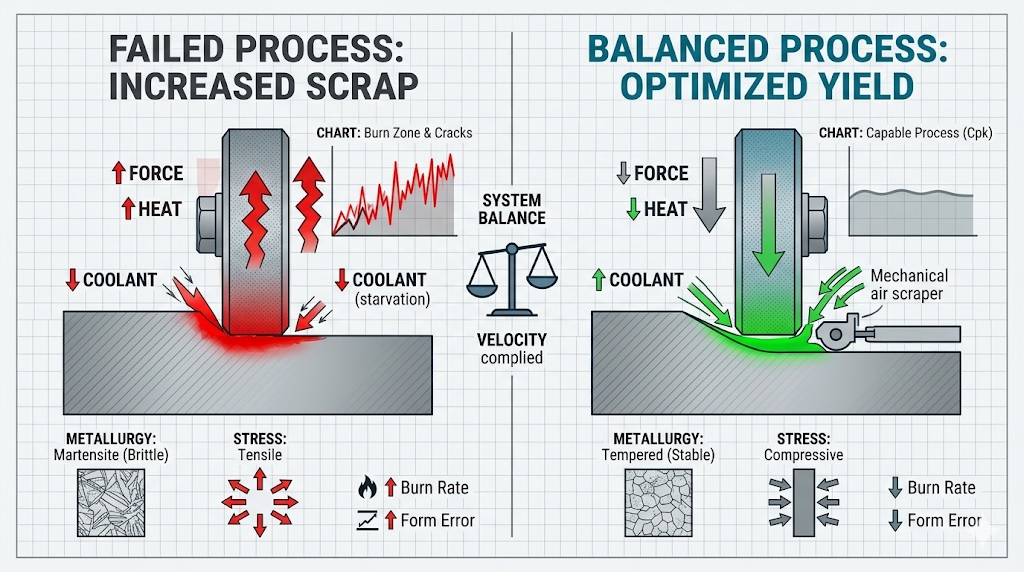
Operating at these high speeds without balancing the mechanical and thermal variables introduces a massive system penalty. Rather than improving output, unguided high-velocity processing causes severe heat retention within the part profile. The coolant cannot penetrate the high-pressure zone created by the fast-spinning wheel, turning a high-efficiency manufacturing strategy into a direct cause of thermal damage. Failing to balance these factors leads to structural defects, micro-cracks, and dimension errors that lower the line’s overall process capability index (Cpk).
Table 1.1: Thermal Energy Shifts and Scrap Risks Across Abrasive Speed Ranges
| Peripheral Wheel Speed (vs) | Workpiece Heat Partition (ε) | Primary Thermal State | Process Security Status |
|---|---|---|---|
| Standard Range (30 – 45 m/s) | 60% – 70% (Alumina Baseline) | Controlled Dissipation via Chips | High Quality Stability |
| High-Velocity Limit (≥ 80 m/s) | 85% – 92% (Extreme Trapping) | Immediate Surface Re-hardening | High Scrap Potential |
This technical imbalance creates a clear cost-performance inversion. Without analyzing the surrounding fluid dynamics and mechanical constraints, introducing high-speed grinding can destabilize production, causing surface burns, tool chatter, and high scrap rates. Overcoming this high-speed trap requires a thorough Deterministic Assessment of the factory floor, evaluating coolant delivery pressures and wheel matrix properties before finalizing an accelerated manufacturing strategy.
2. Failure Mechanism 1: Thermal Phase Transformation and Tensile Residual Stress
The most immediate cause of scrap in high-speed grinding operations is crossing the material’s critical metallurgical threshold. As the peripheral wheel speed (vs) scales upward, the extreme energy flux focused into the contact zone often pushes the workpiece surface temperature past the austenitic transformation point. This rapid thermal cycle acts as a severe Hidden Constraint on component integrity. When the cooling capacity fails to balance this velocity spike, the surface layer undergoes a localized re-hardening process upon cooling, forming a brittle, untempered martensitic structure known as “grinding burn” that completely destroys the component’s Residual Value.
The Stress Inversion: Shifting from Compressive to Tensile Structural Loads
In an optimized precision grinding setup, the mechanical action induces beneficial compressive residual stresses that extend the fatigue life of the part. However, the excessive heat flux generated by unmanaged high velocities causes severe localized thermal expansion in the surface layer, which is compressed by the colder core underneath. When the grinding zone passes, this area contracts rapidly, triggering a permanent structural shift toward Tensile Residual Stress. This structural inversion serves as a major Scrap Trigger, pulling the material matrix apart from within and creating a major barrier to long-term Quality Stability.
The Peak Grinding Zone Temperature Equation
Tmax = Tambient + [ ( 1.13 × ε × ec × vw × ae ) / √( k × ρ × c × vw × lc ) ]
Where ec is specific grinding energy, vw is work speed, ae is depth of cut, and lc is contact length. Spiking wheel speed without scaling the system dynamics drives Tmax straight past the material’s safe tempering limits.
The Micro-Crack Epidemic: Deep Sub-Surface Matrix Cracking
The combination of a brittle, re-hardened martensitic phase and intense tensile residual forces inevitably leads to surface micro-cracking. These cracks often form perpendicular to the grinding direction, extending deep into the sub-surface matrix of the steel. Unlike superficial surface discoloration, these micro-cracks cannot be spotted with the naked eye, requiring advanced NDT methods like Magnetic Particle Inspection (MPI) to identify. Passing these defective layers along the assembly line results in sudden, catastrophic mechanical failures, driving down production yields and creating a massive economic drain on high-precision manufacturing cells.
Table 2.1: Structural Surface States and Stress Profiles Across Thermal Points
| Workpiece Thermal State | Resulting Residual Stress Profile | Sub-Surface Metallurgical Matrix | Component Scrap Status |
|---|---|---|---|
| Cold Grinding Zone (Stable Velocity) | High Compressive Stress (< -300 MPa) | Stable Tempered Martensite | Defect-Free Approved Part |
| Tempering Exposure Zone | Low Tensile Bias (+50 to +150 MPa) | Over-Tempered Softened Ferrite Blocks | Borderline / Reduced Fatigue Life |
| Re-Hardening Burn Point | Severe Tensile Stress (> +450 MPa) | Untempered Brittle Martensite | Immediate Scrap (Micro-Cracking) |
Preventing this thermal scrap loop requires an engineering strategy designed to minimize peak interface temperatures. Simply increasing pump flow will not solve the issue; it demands a thorough Deterministic Assessment of the feed parameters to ensure that the heat flux generated by high-speed processing is safely absorbed by the moving chips or dissipated before it triggers an irreversible phase change in the workpiece material.
3. Failure Mechanism 2: The Hydrodynamic Air Barrier and Fluid Starvation
The second major cause of high-speed grinding scrap is a severe breakdown in fluid delivery, caused by fluid mechanics rather than pump capacity. As the peripheral wheel speed (vs) rises, the rough, porous surface of the grinding wheel acts as a high-velocity fan. This action creates a powerful, fast-moving air boundary layer that wraps around the wheel’s circumference. This phenomenon, known as the Air Blanket Effect, acts as a major Hidden Constraint on the shop floor, generating a localized aerodynamic shield that blocks the fluid stream from entering the cutting zone.
The Aerodynamic Barrier: Fluid Deflection and Sudden Thermal Spikes
When the grinding wheel spins at high velocities, the high-pressure air layer easily deflects standard low-pressure coolant streams. Instead of penetrating the grinding zone to cool the contact point, the fluid is pushed away from the wheel face. This fluid starvation causes immediate dry grinding conditions at the contact point. Without fluid to lubricate the interface, the friction forces increase rapidly, leading to a sudden thermal spike that undermines the process’s Quality Stability.
The Aerodynamic Stagnation Pressure Boundary
Pstagnation = 0.5 × ρair × vs2 ⇒ Pnozzle > Pstagnation
Where ρair is air density and vs is the peripheral wheel speed. Because stagnation pressure scales with the square of the velocity, the required application pressure (Pnozzle) must increase significantly at high speeds to break through the air barrier.
Fluid Starvation Dynamics: Vapor Blankets and Surface Layer Damage
This fluid starvation quickly triggers a severe thermal failure loop. Any small amount of fluid that manages to pass the air barrier immediately vaporizes upon hitting the intense heat of the high-speed grinding zone. This vaporization creates a gas film around the contact area, completely blocking additional liquid coolant from reaching the metal interface. This thermal barrier prevents proper heat extraction, forcing the thermal energy deep into the workpiece profile and permanently lowering the component’s Residual Value.
Table 3.1: Fluid Delivery Behavior and Thermal Protection Across Pressure Levels
| Coolant Delivery Pressure Class | Air Barrier Penetration Capability | Grinding Zone Lubrication State | Process Security Status |
|---|---|---|---|
| Low Pressure (< 0.3 MPa) | Total Deflection (Blocked by Air) | Complete Dry Rubbing (Starvation) | High Scrap Risk (Immediate Burn) |
| Matched Velocity Pressure (1.0 – 2.5 MPa) | Clean Breakthrough (Barrier Cut) | Saturated Fluid Film Cooled | High Quality Stability |
Operating high-speed lines without modifying the fluid dynamics setup creates a significant barrier to process efficiency. Attempting to accelerate wheel speeds while using legacy, low-pressure cooling manifolds ruins manufacturing yields. Overcoming this fluid barrier requires a thorough Deterministic Assessment of nozzle geometry, matches fluid delivery speeds to the wheel’s peripheral velocity, and ensures reliable fluid saturation throughout high-output manufacturing cycles.
4. Failure Mechanism 3: Micro-Chip Thinning and the Loss of Grain Self-Sharpening
The third critical cause of scrap in accelerated grinding operations stems from a fundamental shift in the mechanical cutting behavior at the micro-scale. As peripheral wheel speed (vs) scales upward, the volume of workpiece material assigned to each individual abrasive grain drops drastically. This phenomenon introduces a severe Hidden Constraint to the process window. When the wheel velocity runs too fast relative to the workpiece feed rate, the thickness of the chip carved by each grain falls below a critical threshold, causing the wheel to stop cutting and begin rubbing, which severely damages Quality Stability.
The Rubbing Shift: Moving from Clean Shearing to Pure Friction
Under standard operating parameters, abrasive grains cleanly shear the metal to create micro-chips. However, when high wheel velocities decrease the equivalent chip thickness (heq), the abrasive edges lose the mechanical leverage required to penetrate the hardened steel surface matrix. Instead of clean cutting, the grains slide across the profile in a continuous plowing and rubbing motion. This mechanical friction causes severe localized material displacement, adding dimensional errors to the component profile and lowering its overall Residual Value.
The Maximum Grain Structural Loading and Thickness Drop
heq = ( vw / vs ) × ae ⇒ Fgrain ∝ heq
Where vw is work speed, vs is wheel speed, and ae is depth of cut. Spiking vs without increasing vw drops heq below the cutting edge radius, suppressing the force (Fgrain) required for self-sharpening.
The Glazing Epidemic: Dull Topography and Sudden Scrap Spikes
This low chip thickness completely breaks down the wheel’s natural self-sharpening cycle. Because the normal forces acting on each grain remain below the fracture threshold, the brittle crystal faces never experience the micro-fractures needed to reveal fresh, sharp facets. Instead, the abrasive points flatten out, causing a widespread glazing defect across the wheel face. The dulled wheel stops removing material effectively and generates intense heat friction, creating a primary Scrap Trigger that causes structural re-hardening and surface damage.
Table 4.1: Influence of Material Engagement Modes on Process Capability
| Engagement State Class | Dominant Grain Mechanical Action | Abrasive Face Topography | Process Security Status |
|---|---|---|---|
| Balanced Feed Rate (heq > h_crit) | Clean Micro-Shearing & Chip Form | Controlled Sharp Micro-Fracturing | High Quality Stability |
| Extreme Velocity (h_eq \le h_crit) | Continuous Plowing & Rubbing Friction | Severe Surface Glazing & Dull Facets | Immediate Scrap Risk |
Running high-speed production without keeping chip thickness within a stable window creates a major bottleneck on the factory floor. Forcing faster wheel speeds without a Deterministic Assessment of the workpiece feed velocity ruins production yields. Correcting this glazing loop requires adjusting the entire kinematics envelope, ensuring that each abrasive grain encounters enough material to crack cleanly and maintain a sharp, open wheel surface throughout high-output manufacturing runs.
5. Defect Mitigation Strategy: Engineering the High-Speed Process Window
To prevent the severe thermal phase transformations, aerodynamic fluid deflection, and tool glazing discussed in the previous chapters, manufacturing teams must shift away from trial-and-error setups. Safely exploiting the benefits of high-speed grinding requires a precise, data-driven Strategy. By breaking through the hydrodynamic air barrier, tuning the grinding kinematics, and selecting engineered porous wheel structures, factories can completely eliminate high-speed scrap, stabilize production yields, and protect the component’s Residual Value.
Breaking the Hydrodynamic Barrier: Coherent Nozzles and Scraper Plates
The first step in securing high-speed grinding stability is overcoming fluid starvation. Standard round nozzles must be replaced with specialized coherent jet nozzles that deliver a highly focused, non-turbulent fluid stream. This system integration must be paired with physical air scrapers mounted fractions of a millimeter from the wheel face. The scraper mechanically shears away the high-velocity air blanket, allowing the high-pressure fluid jet to flood the contact zone without deflection, maintaining excellent Quality Stability even at extreme velocities.
The Kinematic Fluid Jet Velocity Matching Target
vjet ≥ vs ⇒ Pnozzle = 0.5 × ρfluid × vjet2
Where vjet is the fluid stream velocity, vs is the wheel speed, and ρfluid is fluid density. To prevent boundary layer deflection, the pump pressure (Pnozzle) must force the fluid jet speed to equal or slightly exceed the wheel speed.
Adaptive Kinematic Tuning: Maintaining the Critical Micro-Chip Thickness
To stop wheel glazing caused by micro-chip thinning, the process kinematics must be completely rebalanced. When engineers increase the peripheral wheel speed (vs), they must simultaneously scale up the workpiece feed rate (vw) or the radial depth of cut (ae). This adaptive adjustment ensures that the equivalent chip thickness (heq) remains safely above the critical cutting threshold, forcing the abrasive grains to fracture under controlled mechanical loads rather than rub against the metal surface.
Table 5.1: Technical Optimization Parameters for High-Speed Defect Elimination
| Process Defect Mode | Engineering Mitigation Tactic | Target Control Specification |
|---|---|---|
| Hydrodynamic Fluid Starvation | Install mechanical air scrapers and high-pressure coherent nozzles. | vjet matches 100% – 120% of vs |
| Grain Glazing & Rubbing | Proportionally increase workpiece feed rate to avoid thin chips. | Maintain heq > prevailing edge radius |
| Thermal Accumulation Scrap | Deploy induced-porosity vitrified wheels with low matrix density. | Porosity volume fraction ≥ 45% |
Engineered Wheel Matrix Structures: Induced Porosity for Thermal Relief
Finally, controlling the heat partition entering the workpiece requires using advanced abrasive wheel architectures. Highly porous, vitrified wheel matrices feature large, interconnected pores that serve a dual purpose: they act as miniature reservoirs to carry coolant directly into the heart of the contact zone and provide ample clearance channels to transport metallic chips away. This open structure drops the thermal partition ratio ($\epsilon$), ensuring that the system can operate at high velocities without experiencing sudden grinding burn epidemics.
Implementing these protective measures transforms high-speed grinding from an unstable source of scrap into a reliable manufacturing asset. Balancing fluid mechanics, kinetic parameters, and abrasive matrix properties provides a clear Deterministic Assessment of the production line. This total optimization loop eliminates thermal and physical defects, allowing factories to securely capture the massive cycle time reductions promised by advanced grinding machinery.
6. Conclusion: Speed is an Asset Only When the System Infrastructure Complies
The intense thermal transformations, fluid starvation traps, and grain glazing mechanisms reviewed across these chapters reveal an important industrial reality: high-speed grinding is not a simple performance dial that can be turned up at will. Forcing a grinding spindle to operate at extreme peripheral velocities without upgrading the surrounding fluid delivery and kinematic parameters transforms an advanced manufacturing cell into a direct source of scrap. Overcoming this productivity bottleneck requires a major Cultural Shift away from treating wheel velocity as an independent variable and toward viewing it as an integrated process architecture.
The Systemic Equilibrium: Balancing Thermal, Fluid, and Kinetic Forces
In a high-precision production environment, achieving the true cycle-time advantages of high-speed processing requires maintaining an exact mechanical and thermal balance. When process engineering teams design a specialized window that eliminates the Hidden Constraints of legacy fluid systems, they protect the component surface from damage. This systematic coordination allows the factory floor to achieve exceptional Quality Stability at aggressive material removal rates, shielding the raw material from tensile failures and securing the tool’s long-term operating life.
The Balanced High-Speed Grinding Stability Index (GSI)
GSI = [ Pnozzle × heq ] / [ vs2 × ε ]
To secure a defect-free process, any upward adjustment in peripheral speed (vs) must be balanced by increasing jet delivery pressure (Pnozzle) and keeping equivalent chip thickness (heq) out of the rubbing zone.
Securing Long-Term Asset Longevity and High Yield Stability
Sustaining these quality improvements over continuous production runs requires establishing a structured, multi-variable monitoring routine on the machine line. Coolant pump pressure gauges, nozzle alignment brackets, wheel face wear profiles, and finished part non-destructive test metrics must be regularly reviewed together. Managing these critical parameters through a shared data system allows engineering groups to maximize the Residual Value of their production assets, protect components from hidden sub-surface micro-cracks, and maintain an exceptionally reliable manufacturing envelope.
Table 6.1: Operational Action Plan for Eliminating High-Speed Grinding Scrap
| Strategic Implementation Phase | Actionable Operational Tactic | Target Performance Metric |
|---|---|---|
| Aerodynamic Pre-Qualification | Install physical air scrapers and high-pressure coherent nozzles to split the air blanket. | Zero fluid starvation burn defects |
| Kinematic Alignment | Coordinate workpiece feed speed alongside wheel velocity changes to protect chip thickness. | Stable self-sharpening action |
| Structural Security Audit | Deploy highly porous vitrified wheel structures to lower the thermal partition ratio. | Protected part Residual Value |
The Ultimate Goal: Aligning Fast Cutting Actions with Balanced Systems
Ultimately, successfully executing a high-speed grinding strategy is about respecting the rigid rules of fluid and thermal Anatomy. When process engineers match accelerated cutting speeds with proper boundary-layer management and correct tool matrix porosity, the machine delivers immaculate, high-integrity parts. This data-backed management framework safely breaks factory floor constraints, eliminates late-stage scrap epidemics, and avoids unexpected re-hardening defects. Balancing machinery parameters with total system limits allows manufacturing lines to secure perfect dimensional results and high output yields, cementing an optimized manufacturing cycle.
References & Technical Resources
- • Malkin, S., & Guo, C. (2007). Thermal Analysis of Grinding. Annals of the CIRP, 56(2), 760-782.
- • Rowe, W. B. (2014). Principles of Modern Grinding Technology (2nd ed.). Academic Press.
- • Webster, J. (1995). Selection of Coolant Delivery Systems for High Speed Grinding. SME Technical Paper, MR95-184.
- • Shaw, M. C. (1996). Principles of Abrasive Processing. Oxford University Press.
Related Technical Reading
To further optimize your high-output operations and prevent costly sub-surface material integrity failures, we highly recommend exploring the following interconnected modules from our master technical directory:
THERMAL METALLURGY (Module 6):
Grinding Burn Causes: Why Overheating Destroys Surface Integrity
FLUID DYNAMICS (Module 12):
Coolant Delivery Optimization in Grinding: Nozzle Design and Flow Rate Effects
PROCESS SELECTION (Module 29):
High-Speed Grinding vs Conventional Grinding: Cost and Risk Trade-Offs