1. Introduction: The Velocity Paradox in Modern Grinding
In the competitive landscape of precision manufacturing, increasing the peripheral wheel speed (vs) is often viewed as the most direct route to enhanced productivity. However, this pursuit of speed introduces a complex Velocity Paradox. While higher speeds can reduce individual grain forces and improve surface finish, they simultaneously push the mechanical and thermal limits of the entire system. Selecting the right equipment specification is not about chasing the highest RPM, but about understanding the Trade-Off Mechanism between safety, thermal integrity, and throughput.
The Complexity of Speed Specification
For many manufacturers, the Mechanism of speed selection is frequently oversimplified. A common misconception is that a spindle rated for 120 m/s is inherently superior to one rated for 60 m/s. In reality, operating at elevated velocities triggers a non-linear increase in Centrifugal Stress and alters the Heat Partition Mechanism at the contact zone. Without a deterministic approach to these variables, “high-speed” can quickly translate into “high-risk,” leading to catastrophic wheel failure or sub-surface metallurgical damage.
Defining the Productivity-Safety Equilibrium
Strategic Specification Selection requires an analysis of the Specific Grinding Energy (us) relative to the wheel’s structural integrity. As velocity increases, the chip thickness decreases, which theoretically improves the Mechanism of Material Removal. However, the auxiliary requirements—such as high-pressure coolant delivery to break the aerodynamic “air barrier”—introduce new operational costs that must be balanced against the gains in cycle time.
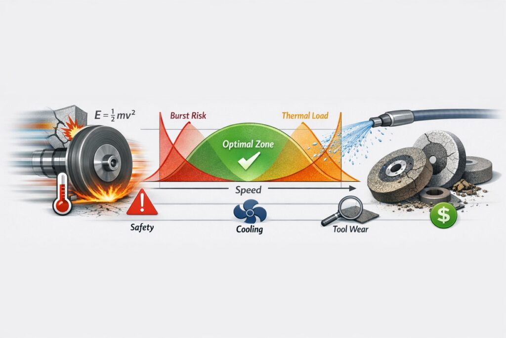
Ekin = 1/2 · m · vs2
Equation 1.1: Kinetic Energy Mechanism and the Exponential Impact of Velocity
Equation 1.1 underscores why speed limits are critical: the kinetic energy (Ekin) inherent in the rotating mass grows with the square of the velocity. This fundamental Mechanism governs why a 20% increase in speed requires a disproportionately larger leap in safety shielding and spindle rigidity. This article will dissect these critical boundaries, providing a roadmap for selecting machine specifications that maximize Net Salable Yield without compromising the Safety Mechanism of the factory floor.
The Velocity Axiom: “Speed is a tool, not a target. The goal of specification selection is to find the Mechanism that aligns peak productivity with the physical safety limits of the abrasive and the thermal tolerance of the workpiece.”
2. The Safety Mechanism: Centrifugal Stress and Burst Speed
The most critical boundary in spindle speed selection is the mechanical integrity of the grinding wheel. As the wheel rotates, it is subjected to an internal Centrifugal Stress Mechanism that pulls the abrasive structure outward. If the wheel speed (vs) exceeds the structural bonding strength of the matrix, the result is a catastrophic “burst,” releasing kinetic energy equivalent to an uncontained ballistic event.
The Physics of Centrifugal Tension
Centrifugal stress (σc) does not increase linearly with speed; it increases with the square of the velocity. This means that doubling the wheel speed quadruples the internal tension acting on the vitreous or resinoid bond. The Mechanism of failure typically initiates at the bore of the wheel, where the tensile stress is at its maximum.
σc ≈ ρ · vs2
Equation 2.1: The Centrifugal Stress Mechanism (where ρ = density of the wheel)
Burst Speed and Safety Factors
To mitigate this risk, international standards (such as ANSI B7.1 or EN 12413) require a significant safety buffer. The “Burst Speed” is the theoretical velocity at which the Mechanism of Bond Fracture occurs. Manufacturers typically set the Maximum Operating Speed (MOS) at a fraction of the burst speed—often providing a safety factor of 1.5x to 2.0x in terms of velocity, which translates to a 2.25x to 4.0x buffer in terms of stress.
The Safety Axiom: “In the Mechanism of high-speed grinding, the spindle does not fail—the wheel does. Choosing a machine with 120 m/s capability is meaningless if your wheel bond Mechanism is only rated for 60 m/s.”
3. The Thermal Mechanism: High-Speed Heat Partition (Rw)
While increasing wheel speed (vs) is a primary driver for productivity, it fundamentally alters the Thermal Flux Mechanism at the contact zone. The critical challenge is managing the Heat Partition (Rw)—the fraction of total grinding energy that is conducted into the workpiece. High-speed grinding (HSG) can be a double-edged sword: it reduces the force per grain but increases the frequency of friction, potentially leading to Grinding Burn if the energy balance is not maintained.
The Chip Thickness and Energy Mechanism
As vs increases, the undeformed chip thickness (hcu) decreases. This results in a reduction of the mechanical force required for chip formation. However, the Mechanism of Size Effect dictates that as the chip becomes smaller, the Specific Grinding Energy (us) increases. This means a higher percentage of the work done is converted into heat rather than useful material removal.
qw = Rw · us · MRR’
Equation 3.1: Heat Flux Mechanism into the Workpiece (where qw = heat flux)
The Air Barrier and Coolant Failure Mechanism
At high peripheral speeds, the rotating wheel acts as a centrifugal fan, creating a high-pressure Boundary Layer of Air. This Mechanism prevents conventional low-pressure coolant from reaching the actual contact zone. If the coolant cannot penetrate this “air barrier,” the Rw value spikes because the heat is not being carried away by the fluid, forcing the workpiece to absorb the thermal energy and causing Sub-surface Tensile Stress.
The Thermal Axiom: “Speed reduces force, but it complicates cooling. To optimize the Mechanism of HSG, the coolant jet velocity must match the peripheral wheel speed to effectively break the aerodynamic barrier and manage the Rw.”
4. Productivity vs. Tool Life: The Speed-Wear Correlation
The relationship between wheel speed (vs) and tool life is governed by the G-Ratio Mechanism—the ratio of the volume of material removed to the volume of wheel wear. In a high-productivity environment, the temptation is to maximize vs to reduce cycle times, but this can lead to a Wear Acceleration Mechanism if the mechanical and thermal limits of the abrasive bond are exceeded.
The Attritious Wear vs. Fracture Mechanism
As wheel speed increases, the Individual Grain Load decreases because the same amount of material is distributed over more abrasive impacts per second. This theoretically shifts the wear Mechanism from “Grain Fracture” (where the abrasive breaks under load) to “Attritious Wear” (where the grain dulls due to friction). While dulling maintains the wheel’s shape longer, it increases the Specific Grinding Energy (us), eventually triggering a thermal failure.
G = Vw / Vs_wear ∝ vsn
Equation 4.1: The Speed-Dependent G-Ratio Mechanism
The Critical Velocity Threshold
Every wheel-material combination has a Critical Velocity Threshold. Beyond this point, the Thermal Softening Mechanism of the bond (especially in resinoid wheels) or the Chemical Diffusion Mechanism (in Alumina grinding of certain alloys) causes wear to accelerate exponentially. Exceeding this limit results in frequent Dressing Cycles, which negates any productivity gains made through higher feed rates.
The Productivity Axiom: “The most productive speed is not the highest speed; it is the speed that maximizes the Net Salable Yield. If higher speed increases your dressing frequency by 20%, you have likely destroyed your Cost-Efficiency Mechanism.”
5. Strategic Spec Selection: Matching Spindle Speed to Material
The final decision in machine procurement must be governed by the Material-Speed Matching Mechanism. Selecting a spindle with a 150 m/s capability for a process that primarily grinds heat-sensitive nickel alloys is an inefficient allocation of capital. To optimize the Total Cost of Ownership (TCO), the spindle’s speed range must be synchronized with the metallurgical and tribalological requirements of the workpiece material.
Ductile vs. Brittle Material Mechanisms
The Mechanism of Chip Removal varies drastically between material classes. For ductile materials like hardened steels, higher speeds (vs) are beneficial as they promote thinner chips and reduce surface roughness. Conversely, for brittle ceramics or glass, the Mechanism of Ductile-Regime Grinding is only achievable at specific, often lower, speed-to-feed ratios to prevent sub-surface cracking.
Spindle Dynamic Stiffness and Vibration Mechanism
As spindle RPM increases, the Vibration Mechanism of the machine tool becomes more sensitive. A high-speed spindle must possess superior Dynamic Stiffness to suppress chatter. When selecting a specification, one must evaluate the Natural Frequency of the spindle-tooling system. If the operating speed coincides with a resonance peak, the resulting surface finish will degrade regardless of the theoretical “high-speed” advantages.
The Matching Axiom: “Never buy speed you cannot cool, and never buy speed that your material cannot tolerate. The Mechanism of the material’s thermal and mechanical resistance is the only true guide to spindle specification.”
6. Conclusion: The Balanced Mechanism of High-Performance Grinding
Optimizing wheel speed is not a pursuit of absolute velocity, but a sophisticated exercise in Mechanism Balancing. As we have dissected, the transition to higher speeds triggers a cascade of physical shifts—from the Centrifugal Stress acting on the wheel bond to the Thermal Partition (Rw) affecting the workpiece integrity. A machine specification that ignores these boundaries is a liability, not an asset.
A Holistic Framework for Spec Selection
To achieve a sustainable competitive advantage, manufacturers must move beyond the “maximum RPM” metric and evaluate their investment through a Data-Driven Selection Mechanism:
- Structural Verification: Ensuring the wheel bond Mechanism (Vitrified, Resin, or Metal) is rated for the intended peripheral velocity with a certified safety factor.
- Thermal Synchronization: Matching coolant delivery pressure and velocity to the wheel speed to effectively break the aerodynamic Air-Barrier Mechanism.
- Economic Justification: Calculating the G-Ratio and dressing frequency to ensure that high speed does not inadvertently erode the Total Cost of Ownership (TCO).
Ultimately, high-performance grinding is achieved at the intersection of mechanical safety and process stability. When the spindle Mechanism is perfectly matched to the abrasive and the material, the result is a process that delivers superior surface integrity, maximized throughput, and a minimized carbon footprint.
The Master’s Rule of Speed
“Precision is the child of control, not velocity. Optimize the Mechanism of the cut first, and the speed of the profit will follow.”
References & Technical Resources
Primary Engineering References
- • Malkin, S., & Guo, C. (2008). Grinding Technology: Theory and Applications of Machining with Abrasives. Industrial Press. (Wheel speed and energy modeling).
- • Rowe, W. B. (2014). Principles of Modern Grinding Technology. William Andrew. (Thermal partition and fluid management).
- • Marinescu, I. D., et al. (2006). Handbook of Machining with Grinding Wheels. CRC Press. (Safety standards and mechanical limits).
Internal Technical Deep-Dive
For further exploration of the speed limits and process mechanics discussed in this report, please refer to the following internal technical modules: