1. Introduction: The Symbiosis of Grinding and Dressing
In the sophisticated world of abrasive machining, a grinding wheel is not a static tool; it is a dynamic cutting organ that requires constant regeneration. The Dressing Mechanism is the vital process of removing dull abrasive grains and clogged metal chips to expose fresh, sharp cutting edges. However, in modern high-precision manufacturing, dressing is no longer an isolated manual task. The Integration of Dressing Units directly into the machine’s CNC architecture has become the primary driver for achieving both Dimensional Accuracy and minimized Cycle Time.
The Interdependence of Surface Topography and Tool Life
The performance of a grinding wheel is defined by its Surface Topography—the specific arrangement and protrusion of active grains. As the wheel grinds, the grains undergo Attrition Wear, leading to increased Grinding Forces and thermal damage (grinding burn). Integrated dressing units provide a deterministic Mechanism to restore the wheel’s sharpness without removing the wheel from the spindle. This symbiosis ensures that the Surface Integrity of the workpiece remains consistent throughout the entire production batch, preventing the “drift” in quality often seen in manual operations.
Defining Integration: Beyond Mechanical Mounting
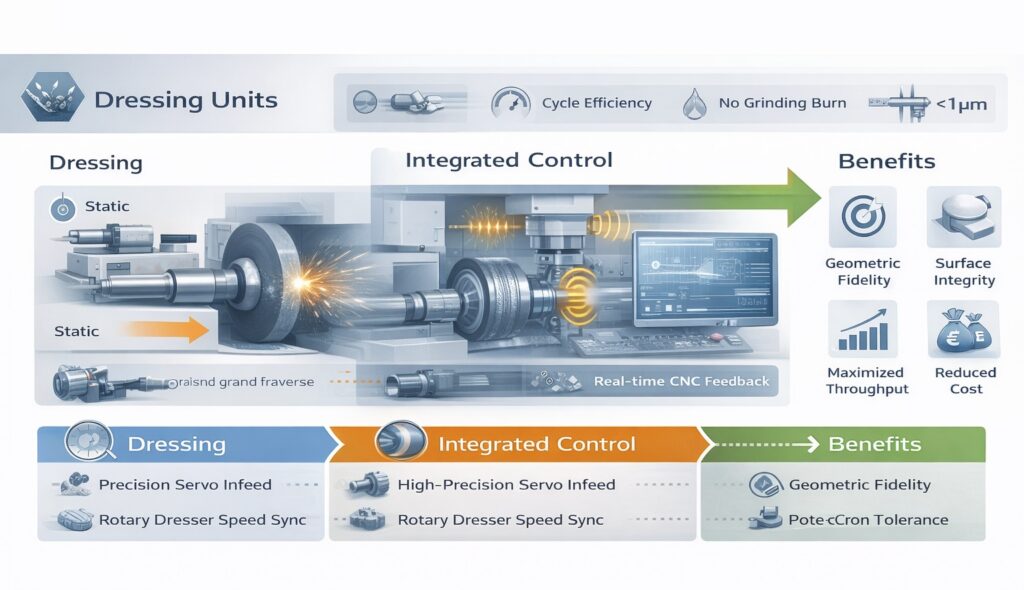
True Dressing Unit Integration involves a seamless digital and mechanical link between the dresser and the machine’s CNC Control Functions. This includes high-precision servo-driven infeed, Acoustic Emission (AE) monitoring for gap elimination, and automated Wheel Wear Compensation logic. By integrating these elements, the machine can execute complex dressing cycles—such as profile truing or continuous dressing—with sub-micron Geometric Fidelity. This level of synchronization is essential for the Process Reliability required in aerospace, automotive, and medical component manufacturing.
Ttotal = Tgrind + Tdress + Tnon-productive
Equation 1.1: Total Cycle Time as a function of integrated dressing efficiency
Operational Focus: Accuracy vs. Productivity
The central theme of this analysis is the dual impact of integrated dressing on Quality Stability and Economic Feasibility. While a frequent dressing Mechanism enhances accuracy, it can also increase Cycle Time if not optimized. Conversely, neglecting dressing to save time leads to high scrap rates and increased Total Manufacturing Cost. By utilizing advanced integrated units, manufacturers can find the “Golden Ratio” where the wheel is dressed exactly when needed, ensuring deterministic precision with maximum throughput.
In the subsequent chapters, we will perform a deep-dive into the Technical Mechanisms of various dressing units, analyze the quantitative effects on Surface Integrity, and provide a framework for Cycle Time Optimization. This journey will establish the integrated dressing unit as the “Heart” of the modern precision grinding machine.
| Integration Aspect | Control Mechanism | Operational Outcome |
|---|---|---|
| Kinematic Precision | Servo-controlled dresser infeed & path. | Maintenance of sub-micron Geometric Fidelity. |
| Sensor Feedback | Acoustic Emission (AE) contact detection. | Minimization of non-productive “Air-Dressing” time. |
| Data Linkage | Real-time CNC work-offset updates (G54-G59). | Constant Dimensional Accuracy post-dressing. |
2. Technical Mechanisms of Integrated Dressing Units
The effectiveness of an integrated dressing unit is defined by its mechanical rigidity and its ability to replicate precise geometric paths. Unlike external dressing stands, integrated units are part of the machine’s structural loop, meaning their Mechanism of operation directly influences the Geometric Fidelity of the grinding wheel. Understanding the kinematic differences between static and rotary systems is essential for optimizing both Dimensional Accuracy and Total Manufacturing Cost.
Static vs. Rotary Dressing Mechanisms
Integrated dressing units typically employ one of two primary mechanisms:
- Static Dressing (Single-point/Blade): This involves a stationary diamond tool that traverses the wheel. The Mechanism is simple and cost-effective but relies heavily on the diamond’s sharp point. It is ideal for simple surface grinding but suffers from tool wear, which can lead to “profile drift” in high-volume batches.
- Rotary Dressing (Diamond Roller): This utilizes a motorized diamond-impregnated roller that rotates against the grinding wheel. The Mechanism allows for higher material removal rates and superior Quality Stability. Because the roller can be profiled, it enables complex form grinding with sub-micron precision.
Structural Stiffness and Vibration Damping
Since the dressing unit is integrated into the machine bed or spindle head, its structural Stiffness is critical. Any deflection during the dressing cycle will translate into an imperfect wheel topography. High-end integrated units utilize Pre-loaded Linear Guides and cast-iron housings to provide maximum damping. This ensures that the Mechanism of grain fracture during dressing is clean and controlled, preventing the introduction of self-excited vibrations that could later manifest as chatter marks.
Ud = bd / sd
Equation 2.1: Dressing Overlap Ratio (Ud) governing the resulting wheel topography
Precision Infeed and Servo-Control
The “In-Process” advantage of integrated units comes from their link to the machine’s CNC Control Functions. The infeed Mechanism—often utilizing high-resolution glass scales—allows for dressing increments as small as 0.1 μm. This precision is vital for Wheel Wear Compensation. Every time the dresser removes material, the CNC instantaneously updates the tool offset, ensuring that the Dimensional Accuracy of the next grinding pass is maintained without manual recalibration.
| Dressing Type | Structural Mechanism | Precision Outcome |
|---|---|---|
| Single-Point Diamond | Point-contact; linear traverse. | High Ra flexibility; moderate tool life. |
| Rotary Plunge | Full profile contact; synchronous rotation. | Maximum geometric fidelity; fast cycle time. |
| CNC Form Dressing | Diamond disc; multi-axis interpolation. | Complex contours; high process reliability. |
3. Accuracy Effects: Geometric Fidelity and Surface Integrity
The integration of a dressing unit is the primary factor determining the Geometric Fidelity of the grinding wheel. Since the wheel is a “negative” of the required workpiece profile, any error in the dressing Mechanism will be directly mirrored on the part. Achieving sub-micron Dimensional Accuracy requires a deterministic control of the dressing parameters to ensure that the wheel’s active surface remains perfectly aligned with the intended design specifications.
Profile Replication and Form Error Control
When grinding complex contours, the dressing unit must replicate the desired profile onto the wheel face with absolute precision. The Mechanism involves synchronized multi-axis interpolation between the dresser and the wheel spindle. Integrated units minimize “stack-up errors” found in external setups, allowing for the maintenance of strict Geometric Fidelity. If the dresser path deviates even by a few microns, it induces a “Form Error” on the workpiece, compromising the Quality Stability of high-precision components like turbine blades or bearing races.
The Mechanism of Surface Roughness (Ra) Generation
The Surface Integrity of the ground part is a direct function of the wheel’s Topography, which is created during the dressing cycle. By adjusting the Dressing Lead (sd) and the speed ratio between the wheel and a rotary dresser, engineers can “program” the resulting Surface Roughness (Ra). A “fine” dressing mechanism creates a closed topography for superior finish, while a “coarse” dressing opens the wheel structure for higher material removal rates. Integrated units allow for this transition to happen automatically within the CNC program, ensuring consistent Quality Stability across varying batch requirements.
Ra ≈ (sd2 / 32 · rd)
Equation 3.1: Theoretical Surface Roughness (Ra) as a function of Dressing Lead (sd) and Dresser Radius (rd)
Wheel Wear Compensation and Thermal Stability
A critical accuracy effect of integrated dressing is the ability to perform real-time Wheel Wear Compensation. As the dresser removes a deterministic layer of abrasive (e.g., 20 μm), the CNC instantaneously updates the tool center point (TCP). This Mechanism prevents “Dimensional Drift” caused by the shrinking wheel diameter. Furthermore, integrated units often include Thermal Compensation algorithms that account for the expansion of the dressing spindle, ensuring that the Dimensional Accuracy remains stable even as the machine reaches its thermal equilibrium during long production runs.
Acoustic Emission (AE) for Precision Touch-off
To ensure maximum accuracy, the dresser must contact the wheel at a precise, repeatable position. Integrated units utilize Acoustic Emission (AE) Sensors to detect the exact micro-second of contact. This Mechanism eliminates the “air-dressing” gap and ensures that the programmed dressing depth is exactly what is removed from the wheel. By closing this feedback loop, the system enhances Process Reliability and prevents over-dressing, which would otherwise waste expensive abrasive material and shorten the wheel’s Life-cycle.
| Accuracy Metric | Dressing Integration Mechanism | Impact on Quality |
|---|---|---|
| Geometric Fidelity | Servo-synchronized profile replication. | Zero-drift contour accuracy (< 2 μm). |
| Surface Finish (Ra) | Deterministic control of Dressing Overlap Ratio. | Mirror finishes without manual polishing. |
| Dimensional Accuracy | Automatic G-code offset updates post-dress. | Constant part sizing across 1,000+ units. |
| Surface Integrity | Regeneration of sharp grains via AE sensors. | Prevention of grinding burn and residual stress. |
4. Cycle Time Optimization: Minimizing Non-Productive Time
In high-volume manufacturing, Cycle Time is the most critical metric for determining Economic Feasibility. The primary advantage of Dressing Unit Integration is the drastic reduction of non-productive time—the “hidden” intervals where the machine is not removing material. By automating the dressing Mechanism and synchronizing it with the grinding path, manufacturers can achieve a significant increase in Productivity without compromising the Surface Integrity of the workpiece.
In-Process Dressing and Reduced Setup Interruption
Traditional grinding processes often require the operator to stop the machine for manual dressing, leading to massive Cycle Time losses. Integrated units allow for In-Process Dressing, where the dressing tool is moved to the wheel during the load/unload sequence or even between roughing and finishing passes. This Mechanism ensures that the wheel is always in its peak cutting state without the need for manual intervention, effectively eliminating the “Setup Drift” and the associated downtime of re-calibrating the Dimensional Accuracy.
Gap Elimination in Dressing via Acoustic Emission (AE)
A significant portion of non-productive time in dressing is spent on the “Air-Dress” phase—the slow approach of the dresser to the wheel to avoid a crash. Integrated units utilize Acoustic Emission (AE) Sensors to detect the exact micro-second of contact. This Mechanism allows the CNC to move the dresser at a “Rapid” feed rate until contact is detected, instantaneously switching to the “Dressing” feed rate. This reduction in approach time can save several seconds per cycle, which translates to a substantial reduction in Total Manufacturing Cost over thousands of parts.
Tcycle = Σ (trapid + tair_cut + tgrind + tdress) → Minimized Tair_cut
Equation 4.1: Optimization of Total Cycle Time (T) through Gap Elimination Mechanisms
The Mechanism of Continuous Dressing (CD)
For high-efficiency processes such as Creep Feed Grinding, Continuous Dressing (CD) is the ultimate optimization strategy. In this Mechanism, the rotary dresser remains in contact with the wheel throughout the entire grinding pass. While this increases Wheel Wear, it allows for extremely high material removal rates (MRR) without the risk of thermal damage or Grinding Burn. By removing the need for separate dressing cycles, CD reduces the overall Cycle Time and ensures a constant Surface Topography, providing unparalleled Process Reliability.
Automated Tool Management and Life-Cycle Prediction
Integrated dressing units provide the data necessary for Predictive Maintenance. The CNC monitors the cumulative volume of abrasive removed from the wheel. This Mechanism allows the system to predict the exact moment the wheel reaches its End-of-Life, prompting a changeover before a failure occurs. This proactive approach prevents the “Quality Collapse” that happens when a worn-out wheel is used, ensuring Quality Stability and maximizing the Life-cycle of expensive diamond dressing rollers.
| Optimization Factor | Technical Mechanism | Cycle Time Benefit |
|---|---|---|
| Non-productive Approach | AE-based Gap Elimination. | 10-20% reduction in dressing interval. |
| Setup Interruption | In-Process automated dressing cycles. | Zero manual intervention downtime. |
| Material Removal Rate | Continuous Dressing (CD) synchronization. | High MRR with zero thermal risk. |
| Coordinate Synchronization | Instantaneous G-code offset correction. | No re-gauging needed post-dress. |
5. Process Synchronization and CNC Feedback Loops
The true power of Dressing Unit Integration lies in the seamless bidirectional data flow between the mechanical dresser and the CNC controller. This Synchronization Mechanism ensures that dressing is not merely a repetitive task but an intelligent response to the evolving state of the grinding wheel. By closing the feedback loop, the machine can maintain Quality Stability and optimize Total Manufacturing Cost through data-driven decision-making.
Real-Time Wheel Wear Compensation (G-Code Integration)
Every time a dressing cycle is executed, the Mechanism of abrasive removal changes the wheel’s radius. To maintain Dimensional Accuracy, the integrated system utilizes a Dynamic Offset Update. The CNC calculates the exact amount of material removed by the dresser and instantaneously adjusts the Work Offsets (G54-G59) or tool length compensation. This ensures that the next grinding pass starts at the correct coordinate, eliminating the need for manual re-gauging and preventing the “Step Error” that compromises Geometric Fidelity.
In-Process Gauging and Dressing Trigger Logic
Modern integrated systems utilize In-Process Gauging to monitor the workpiece diameter in real-time. If the system detects a trend toward the upper tolerance limit—indicating wheel dulling or loading—the CNC automatically triggers a Mini-Dressing Cycle. This Adaptive Mechanism replaces the traditional “Fixed-Interval” dressing, ensuring the wheel is dressed exactly when needed. This prevents over-dressing, which wastes abrasive material, and under-dressing, which leads to Grinding Burn and lost Surface Integrity.
ΔL = f(Ncycles, Vremoval, Pspindle)
Equation 5.1: Mathematical model for predicting tool offset correction (ΔL) based on dressing data
Spindle Load Monitoring and Dresser Feedback
The Mechanism of synchronization also involves monitoring the Spindle Power Consumption. As the wheel dulls, the power required to maintain a constant feed rate increases. The integrated control system uses this data as a feedback signal. When the power exceeds a deterministic Plimit, the CNC initiates a dressing cycle to restore the wheel’s Topography. This closed-loop interaction ensures Process Reliability by preventing catastrophic wheel breakdown and maintaining a consistent Surface Finish (Ra) across thousands of parts.
Dressing Ratio Control for Optimized Grain Protrusion
For rotary dressing, the Speed Ratio (qd) between the dresser and the wheel is a critical variable. The CNC’s Synchronization Logic allows for precise control of this ratio. By modulating the dresser RPM relative to the wheel RPM, the system can control the Mechanism of grain fracture. A positive or negative ratio can be selected to create either a “sharper” or a “smoother” wheel face, providing the flexibility to handle different materials and finish requirements within a single setup, thus enhancing Operational Efficiency.
| Control Loop Module | Synchronization Mechanism | Precision Benefit |
|---|---|---|
| Offset Compensation | Real-time G-code coordinate update. | Maintenance of sub-micron Dimensional Accuracy. |
| Adaptive Dressing | Feedback from In-process gauging/gauges. | Prevention of over-dressing; extended wheel life. |
| Power-Adaptive Feed | Spindle load to dressing trigger linkage. | Zero thermal damage; high Surface Integrity. |
| Speed Ratio Ctrl | Synchronized Spindle/Dresser VFD control. | Tailored wheel topography for specific Ra. |
6. Economic Feasibility: CAPEX vs. Operational Efficiency
The integration of a high-precision dressing unit represents a significant Capital Expenditure (CAPEX). However, the Economic Feasibility of this investment is not determined by the purchase price alone, but by the reduction in Total Manufacturing Cost over the machine’s life-cycle. By analyzing the Mechanism of cost recovery through increased uptime and reduced scrap, manufacturers can determine the true ROI of an integrated system.
Quantifying the Cost of Non-Integrated Dressing
In operations without an integrated Dressing Mechanism, the cost of “Hidden Downtime” is often underestimated. Every manual dressing intervention requires the machine to stop, the operator to adjust the tool, and a subsequent “Trial Cut” to verify Dimensional Accuracy. In a high-volume environment, these interruptions can account for 10-15% of total available production time. An integrated unit eliminates this Mechanism of waste, directly converting idle hours into profitable output.
Wheel Life Extension and Abrasive Cost Recovery
Over-dressing is a common issue in manual or poorly synchronized systems, where operators remove more abrasive than necessary to “be safe.” Integrated units, controlled by Acoustic Emission (AE) feedback, remove only the deterministic amount of material required to restore Surface Integrity. This precision Mechanism can extend the Life-cycle of expensive CBN or Diamond wheels by 30% or more, significantly lowering the Operating Expenditure (OPEX) and improving the overall Economic Feasibility.
ROI = (Σ Sdowntime + Σ Sscrap + Σ Swheel) / CAPEXintegration
Equation 6.1: Return on Investment (ROI) model for integrated dressing systems
The Scrap Reduction and Quality Yield Mechanism
The most immediate financial impact of integrated dressing is the increase in Quality Yield. By maintaining constant Geometric Fidelity and preventing Grinding Burn through automated cycles, the system drastically reduces the scrap rate. For high-value components in the aerospace or medical sectors, preventing just a few scrapped parts per month can justify the CAPEX of the dressing unit. This deterministic Quality Stability is the foundation of a competitive manufacturing strategy.
Labor Optimization and Skill-Gap Mitigation
As the manufacturing industry faces a shortage of highly skilled grinding specialists, the Mechanism of automation becomes even more valuable. Integrated dressing units allow less experienced operators to achieve world-class Surface Roughness (Ra) and Dimensional Accuracy. The “Skill-Built-In” approach reduces the Total Manufacturing Cost associated with specialized labor and training, making the Economic Feasibility attractive even in regions with high labor costs.
| Financial Factor | Integration Mechanism | Economic Benefit |
|---|---|---|
| Machine Uptime | Automated In-process dressing. | 10-15% increase in annual revenue capacity. |
| Abrasive Consumption | AE-monitored precision removal. | 20-40% reduction in wheel replacement costs. |
| Quality Costs | Deterministic profile maintenance. | Significant reduction in scrap and rework. |
| Process Stability | Automated wheel wear compensation. | Higher Cpk; reliable high-volume production. |
7. Conclusion: Achieving Deterministic Precision
The Dressing Unit Integration in modern grinding machines is no longer an optional upgrade but a fundamental requirement for high-performance manufacturing. As we have explored, the Mechanism of automated dressing provides the critical link between Geometric Fidelity and Cycle Time Optimization. By removing the variability of manual intervention, integrated systems transform grinding into a deterministic process where Quality Stability is guaranteed by the machine’s control logic.
The Synergy of Hardware and Software
The success of integrated dressing depends on the harmony between mechanical Stiffness and advanced CNC Control Functions. From Acoustic Emission (AE) sensors to real-time Wheel Wear Compensation, each integrated component works in unison to maintain the peak cutting state of the wheel. This synergy ensures that Dimensional Accuracy and Surface Integrity are preserved across thousands of cycles, maximizing the Life-cycle of both the grinding wheel and the dressing tool.
Future Outlook: AI and Digital Twin Integration
The future of dressing technology lies in Predictive Intelligence. Emerging Digital Twin models can now simulate the dressing Mechanism before the first spark is generated, optimizing the speed ratio and infeed for specific material removal rates. Furthermore, AI-powered Process Monitoring will allow machines to diagnose dresser wear and automatically adjust parameters to maintain Process Reliability. This transition toward “Smart Dressing” will redefine the boundaries of Economic Feasibility in the era of Industry 4.0.
The Master of Regeneration
“In the cycle of precision, the dresser is the guardian of the wheel’s soul. True manufacturing excellence is achieved when the regeneration of the tool is as precise as the creation of the part.”
References & Technical Resources
- • Malkin, S., & Guo, C. (2008). Grinding Technology: Theory and Applications of Machining with Abrasives. Industrial Press Inc.
- • Klocke, F. (2009). Manufacturing Processes 2: Grinding, Honing, Lapping. Springer Science & Business Media.
- • Rowe, W. B. (2013). Principles of Modern Grinding Technology. William Andrew.
- • Marinescu, I. D., et al. (2006). Handbook of Machining with Grinding Wheels. CRC Press.
Internal Technical Deep-Dive
To deepen your understanding of dressing strategies and their impact on operational economics, we recommend the following technical modules: