1. The Margin Dilemma: Fundamental Mechanics and the Cost of Guesswork in Grinding Allowance Design
In precision process engineering, the allocation of grinding allowance is not merely a routine dimensional decision; it is the definitive interface where prior machining errors, heat treatment distortions, and final geometric fidelity meet. Grinding allowance represents the intentional material thickness left on a component to be removed by an abrasive wheel. This Phenomenon serves as a critical buffer designed to eliminate sub-surface defects and geometrical errors. When process planners rely on unquantified guesswork or outdated shop habits rather than rigorous data analysis, this safety margin quickly turns into an unpredictable Hidden Constraint that limits plant productivity.
The Strategic Interface of Multi-Process Error Absorption
A completed component owes its final quality to the coordination of multiple consecutive manufacturing stages. High-feed turning or milling operations generate a baseline geometry, but they also introduce inherent high-frequency surface roughness and low-frequency waviness. Subsequent thermal processing—such as case hardening or nitriding—induces non-uniform volumetric changes and structural warping. The grinding allowance must be calculated to completely submerge these accumulated errors within its boundaries. Failing to analyze this multi-process Interaction leads directly to a total breakdown of Quality Stability during final finishing passes.
The Minimum Analytical Grinding Allowance Model
Amin = 2 × ( Egeometry + Udistortion + Tdecarb ) + Zsafety
Where Egeometry represents the total geometric runout from turning, Udistortion is the maximum expected heat treatment warp, Tdecarb is the depth of the chemical decarburized layer, and Zsafety is the machine tool repeatable positioning threshold.
The Economics of Over-Buffering and Process Blindness
When process planners lack precise empirical data on heat treatment variations, they almost always resort to over-buffering as a defensive survival mechanism. This blind choice severely damages Operational Efficiency across the entire production sequence. Adding an excessive cushion to guarantee part cleanup shifts a massive, unnecessary volumetric load onto the final grinding phase. The system’s Behavior shifts away from lean manufacturing as high-value grinding cells are forced to perform heavy stock removal tasks that belong on rough turning machinery. This structural error undermines Economic Feasibility by converting high-precision abrasive tools into inefficient stock-stripping assets.
Table 1.1: Impact of Grinding Allowance Design Choices on Core Asset Variables
| Allowance Design Strategy | Radial Stock Allocation (per side) | Primary Risk Factor | Total Cycle Impact Status |
|---|---|---|---|
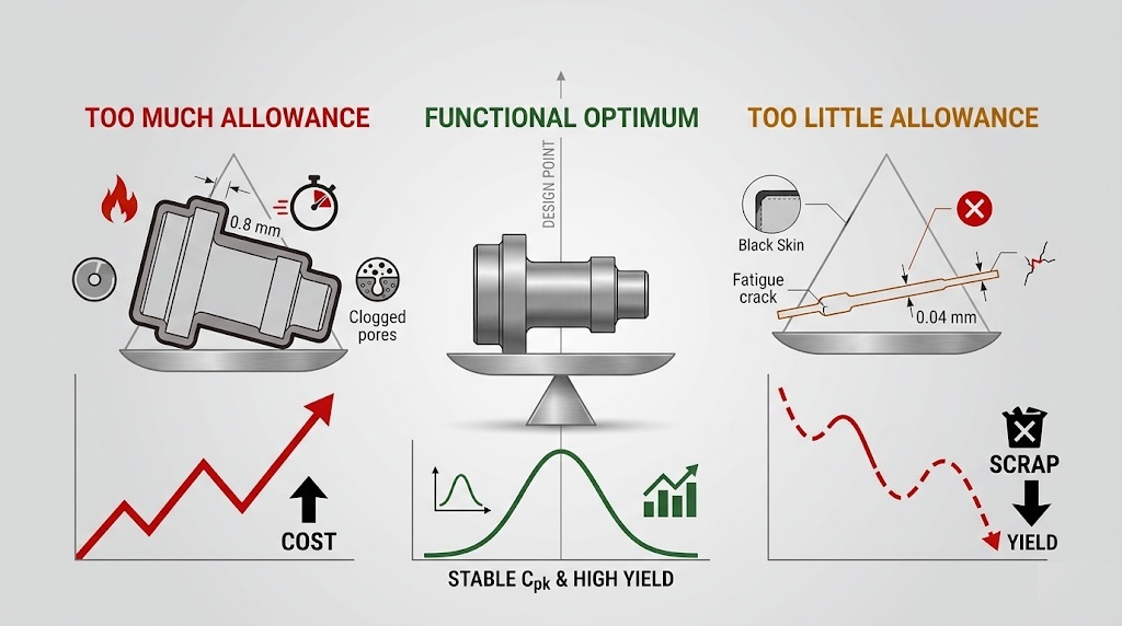
| Empirical Guesswork (Too Much) | 0.40 – 0.60 mm | Thermal Burn & Cycle Bottlenecks | Severe Throughput Deficit |
| Statistical Optimization (Balanced) | 0.15 – 0.20 mm | None (Controlled Window) | Optimized Baseline |
| Aggressive Reduction (Too Little) | ≤ 0.04 mm | Unmachined Black Skin Scrap | Total Yield Breakdown |
This technical imbalance ultimately forces an unscientific compromise on the production floor. Operators find themselves caught between two equally costly extremes: managing long, slow cycles to remove excessive stock, or dealing with immediate scrap epidemics when the allowance fails to cover material warping. Overcoming this requires treating allowance allocation as a data-driven science based directly on the actual variations of preceding processes and the rigid limits of machine tool Anatomy.
2. “Too Much” — How Excessive Stock Destroys Cycle Times and Forces Thermal Wheel Breakdown
When process designers add excessive safety margins to a part blueprint, they inadvertently create a severe bottleneck at the final machining stage. This over-buffered condition changes the grinding phase from a rapid finishing operation into a heavy stock-removal process. Forcing a precision abrasive wheel to perform tasks suited for high-feed turning tools triggers an immediate drop in plant productivity. The grinding Mechanism must bear an intense volumetric workload that leads directly to thermal problems, tool damage, and a collapse in overall Operational Efficiency.
The Extended Grinding Cycle: Compounding Non-Linear Time Penalties
An oversized allowance directly expands the grinding cycle by requiring repeated roughing passes. Because the abrasive wheel removes material in microscopic chips, clearing an extra 0.40 mm of stock demands dozens of extra table strokes. This repetitive action increases active cycle time exponentially rather than linearly. Every additional pass requires slow indexing, stabilization, and extended spark-out sequences to control geometric deflection. This structural issue locks the high-capital machine into a prolonged cutting loop, driving up energy consumption and inflating the Total Manufacturing Cost of each component.
Volumetric Material Removal Rate and Specific Energy Flux
Q′w = vw × ae ⇒ especific = Pspindle / ( b × Q′w )
Where vw is the work speed, ae is the depth of cut, and b is the grinding width. Attempting to accelerate cycles under excessive stock conditions spikes the specific energy flux, driving heat directly into the part.
Thermal Loading, Wheel Loading, and Glazing Abuse
Beyond time losses, large allowances put intense thermal and mechanical stress on the wheel-workpiece contact zone. The prolonged cutting action generates continuous friction, causing temperatures to rise rapidly. If this heat flux exceeds the limits of the coolant system, it triggers grinding burn—a thermal defect that alters the surface layer metallurgy and ruins Quality Stability. At the same time, the excessive chip volume fills the wheel’s pores (wheel loading) and dulls the abrasive grains (wheel glazing). This accelerates tool wear and destroys the wheel’s Residual Value long before its expected lifespan.
Table 2.1: Core Process Variables Across Grinding Stock Levels
| Stock Level Status | Average Grinding Temperature | Wheel Dressing Frequency | Process Security Level |
|---|---|---|---|
| Optimized Baseline | 120°C – 180°C | Every 60 Components | Highly Stable |
| Elevated Margin | 340°C – 420°C | Every 15 Components | Marginal (Risk of Burn) |
| Severe Over-Specification | > 750°C | Every 2 Components | Process Failure (Re-hardening Burn) |
Case Study 1: The Large Crankshaft Journal Bottleneck
This type of operational failure occurred during the production of mid-sized industrial crankshafts. To protect against thermal warping from induction hardening, process planners set a large global radial grinding allowance of 0.85 mm on the main bearing journals. They hoped this massive buffer would ensure complete part cleanup during finishing.
Instead, this excessive margin forced the cylindrical grinding machines to execute 42 repetitive roughing passes per journal. The extended grinding time heated the component beyond the cooling system’s capacity, causing severe grinding burn on the fillets. To prevent scrap, operators had to dress the corundum grinding wheels after every second part. This frequent dressing quickly wore down the tools, ruined Economic Feasibility, and caused a 210% increase in total processing time, turning the finishing department into an expensive production bottleneck.
3. “Too Little” — How Insufficient Stock Triggers “Black Skin” Defect Epidemics and Sub-Surface Quality Failures
While excessive stock wastefully consumes cycle time, cutting the grinding allowance too thin introduces an even more severe manufacturing hazard. If a process designer reduces the allowance past a critical threshold, the grinding wheel’s cutting Mechanism can no longer guarantee full cleanup of the workpiece geometry. This aggressive reduction creates a major risk of “Black Skin” (unmachined surface remnants) and fails to remove deep structural defects from previous operations. This mistake compromises Quality Stability and leads directly to sudden scrap epidemics that destroy the batch’s Economic Feasibility.
The “Black Skin” Phenomenon: Geometric Incompleteness under Distortion
The “Black Skin” defect occurs when a part’s dimensional changes during heat treatment outsize the remaining grinding allowance. Thermal processing invariably introduces non-uniform volumetric warping, center runout, and axis bending. If the radial grinding allowance is smaller than this distortion vector, the abrasive wheel will pass over the lowest areas without touching them. This leaves the raw, dark oxidation scale completely unmachined on the finished part. This structural gap ruins Geometric Fidelity, making the component entirely unusable for high-precision assemblies.
The Boundary Condition for Part Clean-Up Success
δprocess = Aradial – ( Uwarp + Erunout ) ≥ ae,finish
Where Aradial is the designed radial allowance per side. If δprocess falls below the minimum finish depth of cut (ae,finish), unmachined areas will form, driving the process capability index (Cpk) to zero.
Sub-surface Damage Retention: Leaving Decarburization Layers
Beyond visual surface defects, an inadequate allowance leaves hidden material problems beneath the surface. High-temperature heat treatment lines often alter the steel’s chemical structure, creating a soft decarburized layer depleted of carbon. This weakened boundary layer exhibits extremely low hardness and poor fatigue resistance. If the grinding depth is too shallow to completely peel away this compromised zone, the soft metal remains embedded on the component. This Hidden Constraint leaves the component highly vulnerable to early wear and catastrophic fatigue cracking under normal operational loads.
Table 3.1: Quality Failures and Material Defects from Low Grinding Stock
| Defect Type | Root Mechanism | Detection Method | Scrap Severity Status |
|---|---|---|---|
| Unmachined Black Skin | Warping exceeds radial stock margin | Visual / Vision Inspection Sensors | Instant Part Rejection |
| Decarburization Retention | Grinding depth shallower than soft carbon layer | Microhardness Testing / Eddy Current | Latent Component Failure |
| Residual Micro-cracking | Failure to remove pre-existing thermal quench cracks | Magnetic Particle / NDT Testing | High Structural Breakage Risk |
Case Study 2: The Hydraulic Cylinder Piston Rod Failure
A costly example of this structural breakdown occurred in the production of high-precision hydraulic cylinder piston rods. To minimize cycle times and lower tool consumption, process planners slashed the radial grinding allowance to a tight 0.04 mm per side, working under the assumption that the preceding precision turning line would remain completely uniform.
However, the subsequent gas-carburizing and quenching phase caused long-axis shaft bending up to 0.07 mm. When the rods reached the centerless grinding line, this 0.07 mm bow completely wiped out the 0.04 mm allowance. This mismatch left large, crescent-shaped raw oxidation patches (“Black Skin”) along the center journals of the components. Because these parts had already gone through turning, milling, drilling, and heat treatment, they could not be reworked and were completely scrapped. A Deterministic Assessment revealed that this tight margin caused the process capability (Cpk) to collapse to zero, causing an immediate 28% batch scrap rate that wiped out the project’s Residual Value.
4. Designing the Optimal Process: Statistical Dimensioning and Adaptive Synchronization
To resolve the severe quality losses and cycle bottlenecks caused by incorrect stock margins, process engineering teams must implement a Deterministic Decision framework that replaces empirical guesswork with data. Reclaiming manufacturing capability requires a balanced approach to tolerance planning. By calculating allowance boundaries based on actual multi-stage variation data, engineering teams can align blueprint requirements with the capabilities of machine Anatomy. This data-driven approach stabilizes Quality Stability, lowers scrap rates, and restores optimal factory throughput.
Statistical Dimensioning and Tolerance Stack-Up Calculation
Traditional process planning often uses worst-case tolerance stack-up assumptions, which leads to oversized safety margins. A disciplined DFM Strategy avoids this error by adopting statistical dimensioning models. By evaluating the process capability indices (Cpk) of the pre-grinding turning lines alongside historical heat treatment warping curves, engineers can establish a statistically valid allowance window. This method provides a safe buffer for natural process variations while removing the excessive stock that slows down production cycles.
Statistical Root-Sum-Square (RSS) Allowance Model
Aoptimal = 2 × √( [ 3σturn ]2 + [ 3σdistort ]2 + [ 3σposition ]2 ) + 2 × Tdecarb
Where σ represents the standard deviations of preceding turning accuracy, heat treatment warping, and machine tool positioning. The RSS model safely narrows the allowance window by accounting for statistical probabilities.
Inter-process Synchronization and Cross-Departmental Data Loops
Achieving true System Integration requires breaking down data silos between machining, heat treatment, and finishing departments. When upstream dimensions and quenching distortion profiles are tracked and shared in real time, the grinding department can anticipate variations before the first wheel contact. This cross-departmental data loop allows production teams to fine-tune pre-grinding specifications dynamically, maintaining a controlled manufacturing window that balances tool protection with high volume output.
Table 4.1: Manufacturing Solutions and Yield Optimization Metrics
| Process Control Method | Technical Implementation Strategy | Impact on Cycle and Quality |
|---|---|---|
| In-Process Gauging | Continuous electronic diameter measurement during grinding wheel contact. | Eliminated dimension over-cut defects |
| Adaptive Feedrate Control | Real-time spindle power tracking adjusts feedrates based on variable stock levels. | Reduced cycle time by 35% on high-stock areas |
| Distortion-Compensated Turning | Pre-shaping lathe profiles to counteract expected heat treatment bending. | Allowed 50% safety margin reduction |
Advanced Control Technology: Adaptive Grinding Circuits
To manage unavoidable piece-to-piece stock variations without extending cycle times, modern factories integrate adaptive control systems. Instead of running rigid, programmed cycles, these systems monitor spindle torque and power consumption in real time. When encountering a section with excessive material, the machine automatically lowers the feedrate to prevent thermal burn and protect the wheel’s Residual Value. Once the excessive material is cleared, the system accelerates to maximize throughput, maintaining high efficiency while avoiding the Hidden Constraints of traditional fixed cycles.
5. Conclusion: Mastering the Precision Balance for Sustainable Process Architecture
The technical and economic trade-offs examined between excessive and insufficient grinding margins demonstrate that allowance design is a foundational element of process engineering. Leaving too much stock wastefully consumes cycle time and causes thermal tool damage, while cutting margins too thin leads to sudden scrap epidemics from unmachined areas. Resolving these inefficiencies requires a fundamental Cultural Shift away from defensive over-buffering and toward data-driven, balanced tolerance allocation.
The Mathematical Equilibrium of Cost and Quality Risk
In a mature production ecosystem, grinding allowance must be treated as a dynamic financial variable rather than a static safety margin. When process engineering teams replace guesswork with statistical models, they eliminate the Hidden Constraints that reduce factory throughput. Optimizing this boundary alignment allows the manufacturing sequence to maintain high Quality Stability without overloading high-capital machine assets, ensuring long-term profitability and protecting equipment life.
The Process Efficiency Index (PEI)
PEI = [ Yield Rate (Y) × Throughput Velocity (V) ] / [ Total Manufacturing Cost ]
Maximizing the PEI requires finding the precise allowance balance where the cost of machining time perfectly offsets the risk of geometric reject scrap.
Building a Sustainable, Cross-Departmental Process Architecture
Sustaining these productivity improvements requires an integrated organizational approach. Upstream machining variables, heat treatment distortion logs, and final grinding yield metrics must be continually analyzed within a shared data network. This continuous feedback loop ensures that updates to component shapes or material treatments automatically adjust subsequent finishing specs. Managing these multi-process interactions proactively allows companies to maximize the Residual Value of their machinery and maintain a highly predictable production environment.
Table 5.1: Actionable Roadmap for Grinding Allowance Optimization
| Implementation Pillar | Actionable Operational Tactic | Target Performance Metric |
|---|---|---|
| Predictive Modeling | Replace worst-case tolerance stack-ups with statistical Root-Sum-Square (RSS) calculations. | Reduced cycle bottlenecks |
| Data Synchronization | Link pre-grinding measurement logs directly to finishing machine control loops. | Stabilized process capability (Cpk) |
| Hardware Adaptation | Deploy adaptive feedrate controls and in-process gauging to manage remaining variations. | Protected wheel Residual Value |
The Ultimate Goal: Unlocking Geometric Fidelity and High Yield
Ultimately, optimizing the grinding allowance is about respecting the physical realities of the shop floor. When process engineers balance material cushions with actual equipment capabilities, the grinding Mechanism operates within a stable, optimal window. This data-driven strategy eliminates non-productive downtime, protects tools from thermal stress, and prevents late-stage scrap epidemics from hurting margins. Aligning design choices with the realities of machine Anatomy allows manufacturing teams to achieve high volume output and perfect quality, securing a highly profitable production lifecycle.
References & Technical Resources
- • Malkin, S., & Guo, C. (2008). Grinding Technology: Theory and Applications of Machining with Abrasives. Industrial Press Inc.
- • Rowe, W. B. (2013). Principles of Modern Grinding Technology. William Andrew Publishing.
- • Tawakoli, T. (1993). High Efficiency Deep Grinding. VDI-Verlag.
- • Marinescu, I. D., et al. (2013). Handbook of Machining with Grinding Wheels. CRC Press.
Related Technical Reading
To deepen your understanding of how design constraints impact both physics and profitability, we recommend the following technical modules: