1. Introduction: The Geometry of Light and the Challenge of Aspheres
In the world of precision optics, the transition from spherical to Aspheric geometry represents a leap in optical performance but a nightmare in manufacturing stability. While spherical surfaces are “self-correcting” through natural kinematics, an aspheric surface has no single center of curvature. Every point on the lens is a unique coordinate in a complex mathematical function. At this level, manufacturing is no longer a polishing problem—it is a force, stiffness, and thermal control problem disguised as optics.
Form Error vs. Roughness: The Precision Gap
For high-end applications like semiconductor lithography or aerospace IR sensors, achieving a “mirror finish” (low Ra) is insufficient. The critical metric is Form Error, often measured in fractions of a wavelength (λ/10 or λ/20). A surface can be perfectly smooth yet optically useless if its geometry deviates by a few hundred nanometers from the design intent. This is where the engineering discussed in our previous chapters on spindle run-out and machine stiffness becomes the literal difference between a functional lens and a piece of scrap glass.
The Importance of Spatial Frequency (PSD)
In aspheric machining, we move beyond “average error” to Power Spectral Density (PSD). Mid-to-high spatial frequency errors—often caused by microscopic spindle vibrations or tool path discretization—create “ghosting” and light scattering that cannot be polished away. To eliminate these, the machine’s dynamic stiffness must be near-perfect. We are not just removing material; we are controlling the Spatial Frequency Function of the surface through deterministic mechanical engagement.
The Aspheric Axiom: “In the nanometer realm, the machine does not just cut the shape; the machine is the shape. Any instability in the spindle or a 1mK change in temperature is directly engraved into the optical function of the lens.”
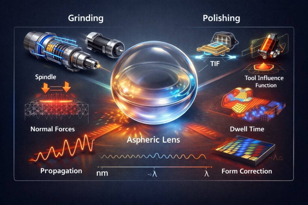
2. Ultra-Precision Grinding: The Deterministic Generation of Form
Unlike conventional grinding, which aims for rapid volume removal, ultra-precision aspheric grinding is a deterministic form-generation process. Here, the grinding tool path is the mathematical derivative of the desired optical function. Because aspheric surfaces lack symmetry, the machine must maintain perfect synchronization between its axes. At this scale, the grinding wheel does not just “sand” the surface; it acts as a single-point generator where the engagement of every individual diamond grain must be controlled.
Ductile Regime Grinding: Machining Glass Like Metal
The greatest challenge in machining optical glass or ceramics is their inherent brittleness. Standard grinding creates micro-cracks (fracture mode). However, by controlling the Critical Depth of Cut (dc) to a level typically below 100 nm, we enter the Ductile Regime. In this state, the energy required to propagate a crack is higher than the energy required for plastic flow. The result is a “mirror-like” ground surface with minimal sub-surface damage (SSD), which is essential for the subsequent polishing stages.
Normal Force (Fn) as a Form Projection
In aspheric grinding, any fluctuation in the Normal Force (Fn) is directly projected onto the workpiece as a form error. Because the curvature of an asphere changes constantly, the contact area between the wheel and the lens also changes. This variation in contact mechanics leads to fluctuating forces. If the spindle or the machine frame lacks sufficient Static Stiffness, these force changes cause the tool to “push off,” creating nanometric deviations that destroy the optical wavefront.
Deterministic Tool Path: The Function of Shape
The tool path in aspheric grinding is not a simple linear move; it is a Form-Generating Function. To maintain the accuracy of this function, the grinding wheel must be perfectly Trued to a sub-micron radius. Any error in the wheel’s own geometry or its centering (run-out) will be mathematically “convolved” into the lens shape, creating systematic errors that polishing cannot easily fix.
The Deterministic Axiom: “Aspheric grinding is not about removing material; it is about mapping a mathematical function onto a physical substrate. The grinding wheel is the pen, and the machine’s stiffness is the steady hand required to draw with nanometric precision.”
3. The Spindle as the Arbiter of Aspheric Fidelity
As established in our previous discussions on spindle dynamics, the spindle is the mechanical heart of the process. In aspheric machining, however, the spindle’s role shifts from a simple rotation provider to the arbiter of spatial frequency. At the nanometer scale, traditional metrics like “Total Run-out” are insufficient. We must focus on the Non-Repetitive Run-out (NRR), as this is the invisible force that creates uncorrectable errors in the optical wavefront.
Why NRR < 50 nm is the Threshold
Repetitive run-out (errors that occur once per revolution) can often be compensated for through CNC offsets or truing. However, NRR represents asynchronous vibrations—noise in the system that varies with every turn. In aspheric grinding, NRR creates mid-spatial frequency ripples on the lens surface. If the NRR exceeds 50 nm, these ripples become large enough to cause light scattering, resulting in a lens that looks clear but fails the MTF (Modulation Transfer Function) test. This is why Air Bearing Spindles, with their near-zero NRR, are the industry standard for high-end aspheres.
The Failure of Rolling Elements in Optics
High-stiffness rolling element spindles, while excellent for heavy-duty turning, often fail in aspheric optics. The reason lies in the ball-pass frequencies. As the balls circulate, they generate micro-vibrations at specific frequencies that coincide with the spatial frequencies of the lens. These “vibration signatures” are engraved into the glass, creating a diffraction grating effect. For aspheres, Damping + Low Run-out is far more valuable than pure static stiffness.
Air vs. Hydrostatic: Choosing the Right “Fluid”
While air bearings offer the lowest NRR, Hydrostatic spindles are sometimes preferred for large-aperture aspheres (e.g., telescope mirrors). The higher viscosity of oil provides superior Squeeze-Film Damping, which is essential for stabilizing the large, heavy grinding wheels used in these processes. The choice depends on a delicate balance: Air for speed and nano-roughness; Hydrostatic for mass and stability.
The Spindle-Optic Link: “In aspheric machining, the spindle run-out is not a measurement—it is a surface finish. If you can measure the vibration in the spindle, you will see it in the lens. The spindle’s NRR is the ultimate limit of your optical wavefront.”
4. The Transition Trap: Grinding to Polishing
One of the most dangerous myths in precision manufacturing is that polishing is a “corrective” process for poor grinding. In reality, polishing is a surface-smoothing process that follows the geometric path laid down by the grinding wheel. If the grinding stage fails to provide the correct form fidelity or leaves behind deep structural damage, polishing will not only fail to fix the error—it will often amplify it.
Sub-Surface Damage (SSD): The Invisible Saboteur
Even a ground lens that looks “mirror-like” can harbor Sub-Surface Damage (SSD)—micro-cracks and strained crystalline structures that extend 5 to 50 μm into the material. If these cracks are not fully removed by the “Pre-polish” stage, they act as stress concentrators during final polishing. As material is removed, these hidden fractures can “bloom,” leading to unpredictable removal rates and localized form errors that destroy the λ/20 specification.
“Mirror Finish” vs. “Correct Form”
Engineers often mistake a low Ra value for a successful process. However, in aspheric optics, Form Accuracy is the king. A lens can have a sub-nanometer roughness but a 2 μm form error, making it useless. Polishing tools, especially soft laps, tend to “dub” or round off the edges of an asphere, a phenomenon known as Edge Roll-off. This happens because the polishing pressure is not uniform across the varying curvature of the aspheric profile.
The Necessity of Deterministic Grinding
To avoid the transition trap, the grinding stage must be Deterministic. This means the grinding machine must leave a surface where the form error is already within the “Capture Range” of the polishing tool—typically less than 1 μm for MRF (Magnetorheological Finishing). If the grinding error is too high, the polishing time increases, which in turn increases the risk of thermal drift and “Mid-Spatial Frequency” errors.
The Transition Axiom: “Polishing does not correct form errors—it amplifies what grinding left behind. A nanometer gained in the grinding stage saves a millimeter of headache in the polishing hall.”
5. Deterministic Polishing: The Inverse Problem
Once the grinding stage has established the macro-geometry, the final wavefront correction is achieved through Deterministic Polishing. Unlike traditional “full-lap” polishing which relies on random movement, deterministic methods like MRF (Magnetorheological Finishing) and CCP (Computer Controlled Polishing) treat material removal as a mathematical Inverse Problem. We do not simply rub the lens; we solve an equation where the solution is the time the tool spends at each coordinate.
MRF: The Magic of Magnetorheological Fluids
MRF is the gold standard for high-end aspheres. It uses a magnetic fluid containing abrasive particles that hardens into a “polishing ribbon” when it passes through a magnetic field. Because the fluid is compliant, it perfectly conforms to the local curvature of the asphere, eliminating the “mismatch” problem of rigid tools. More importantly, the removal rate is extremely stable, allowing for predictable nanometric correction.
Dwell Time = The Correction Function
The “magic” of deterministic polishing lies in the Dwell-Time Algorithm. The machine takes a measurement of the lens (Interferometry) and compares it to the ideal design. The difference is the “Error Map.” To fix this, the machine calculates exactly how long the tool must stay at each point to remove just enough material. High points get more dwell time; low points get less.
The Tool Influence Function (TIF)
Every polishing tool has a Tool Influence Function (TIF)—essentially its “footprint” of material removal. In aspheric machining, the TIF must be smaller than the spatial frequency of the errors we are trying to fix. If the TIF is too large, it acts as a low-pass filter, smoothing out roughness but failing to correct the mid-spatial ripples (PSD) caused by the grinding spindle’s NRR.
The Inverse Axiom: “Deterministic polishing is not a mechanical removal process; it is a mathematical correction. The tool is simply a physical execution of a software algorithm that compensates for the mechanical imperfections of the grinding machine.”
6. The Integral Effect: Thermal, Vibration, and Time
At the λ/20 frontier, we no longer treat the machine as a collection of static parts. It becomes a living system where Thermal Drift, Seismic Vibration, and Time-Dependent Compliance converge. In the nanometer realm, the “Thermal Axiom” we discussed in previous chapters takes its most extreme form: a temperature fluctuation of just 0.001°C (1 mK) can cause a refractive index change or a structural expansion that exceeds the entire error budget of the lens.
The 1 mK Disaster: Why Warm-up is Not Stability
Precision aspheric machines must reside in “Class 10” environmental chambers where the air temperature is controlled to within ±0.01°C. However, the machine’s internal heat—from the air bearing’s air expansion and the controller’s electronics—creates Micro-Thermal Gradients. If the machine has not reached absolute thermal equilibrium, the spindle will “drift” axially by 10-20 nm per hour. In a deterministic polishing cycle that takes 5 hours, this drift results in a 100 nm form error—completely ruining the optical wavefront.
Seismic Isolation: The Battle Against the Floor
Even if the spindle is perfect, external vibrations from the factory floor—trucks passing outside or nearby elevators—can translate into the machine bed. In aspheric grinding, these low-frequency vibrations create Long-Wavelength Form Errors. Ultra-precision machines must be mounted on active pneumatic isolation systems that filter out vibrations down to 0.5 Hz. Without this, the “deterministic” path is constantly being modulated by the “random” noise of the building.
Metrology: The Uncertainty Principle of Optics
In aspheric machining, you cannot fix what you cannot measure. The limitation of the process is often the Metrology Loop. Measuring a λ/20 surface requires an interferometer that is itself thermally stabilized. If the measurement taken after grinding is off by 10 nm due to a thermal pocket in the metrology room, the “Inverse Problem” solved in the polishing stage will be based on false data, effectively “polishing in” an error that didn’t exist.
The Environmental Axiom: “The machine is a thermometer. The floor is a speaker. At the nanometer level, the distinction between ‘process’ and ‘environment’ disappears. To master the asphere, you must first master the room.”
7. Industrial Realities: Where Nanometers Turn Into Profit
Ultra-precision aspheric machining is not merely an academic exercise in physics; it is the fundamental enabler of the modern digital and defensive economy. The ability to manage the force-stiffness-thermal trinity allows industries to move from mass production to “Mass Precision.” From the lenses in your pocket to the mirrors in deep space, the engineering discussed in this series is the invisible bridge between theoretical optics and functional hardware.
Semiconductor Lithography (EUV)
The most demanding application of aspheric technology is Extreme Ultraviolet (EUV) Lithography. The mirrors used in these systems require form accuracies measured in picometers and surface roughness at the atomic level. Any error in the spindle run-out or the deterministic polishing dwell-time would result in a failure to focus light at the 3nm node, halting the global advancement of microchips.
Consumer Electronics: AR/VR and Mobile Optics
For AR/VR headsets, the challenge is Lightweighting. Aspheric lenses allow for thinner, lighter optical stacks that eliminate the “screen door” effect. Here, the focus is on high-volume deterministic grinding. The machine must maintain its thermal stability over thousands of cycles to ensure that every lens produced has the exact same wavefront signature, ensuring user comfort and immersion.
Aerospace and Defense: IR Vision Systems
Infrared (IR) optics often use brittle materials like Germanium or Silicon. As discussed in Chapter 2, Ductile Regime Grinding is critical here to avoid fracture-mode failure. These aspheric surfaces allow missile guidance systems and satellite cameras to achieve high-resolution imaging in compact form factors, where every gram of weight saved equals thousands of dollars in fuel efficiency.
The Industrial Axiom: “Precision is the ultimate competitive moat. In the nanometer economy, the companies that master the integration of spindle dynamics, deterministic polishing, and environmental control are the ones that define the future of technology.”
References & Internal Technical Resources
Primary Engineering References
- • Shore, P., & Morantz, P. (2012). Ultra-precision: Enabling our Future. Philosophical Transactions of the Royal Society A. (Framework for nanogrinding and aspheric generation).
- • Klocke, F. (2011). Manufacturing Processes 2: Grinding, Honing, Lapping. Springer. (Mechanics of ductile regime grinding in brittle materials).
- • Evans, C. J., & Parks, R. E. (1996). Precision Engineering: Polishing and Metrology. Elsevier. (Deterministic finishing and the inverse problem in optics).
Internal Technical Deep-Dive
To see how spindle dynamics and process stability apply to this high-end aspheric workflow, refer to these core modules: