1. Introduction: The Spindle as the Process Foundation
In the architecture of a precision grinding machine, the Wheel Spindle is not merely a rotating shaft; it is the fundamental conduit through which electrical energy is converted into material removal. The spindle acts as the mechanical heart of the system, and its performance dictates more than 60% of the final part’s quality. While the machine bed provides damping and the axes provide positioning, it is the spindle that must maintain sub-micron rotational accuracy while resisting the intense normal forces (Fn) generated at the grinding interface.
The Impact of Rotational Fidelity
The primary metric of a spindle’s quality is its Run-out (both radial and axial). Any deviation in the axis of rotation is directly mapped onto the surface of the workpiece. High run-out leads to inconsistent chip thickness for each abrasive grain, resulting in Harmonic Chatter and a degradation of surface finish (Ra). In precision grinding, where tolerances are often measured in microns, a spindle with a run-out exceeding 1μm can render the entire process incapable of meeting modern aerospace or medical standards.
The Stiffness-Damping Paradox
An ideal spindle must possess two contradictory attributes: high Static Stiffness (kstatic) to prevent deflection under heavy loads, and high Dynamic Damping to absorb vibrations. A rigid but poorly damped spindle will vibrate excessively when encountering process disturbances, while a well-damped but compliant spindle will flex, leading to “Mean Shift” errors in the Cpk analysis. The selection of the bearing technology—whether rolling element, hydrostatic, or aerostatic—is essentially an engineering compromise between these two physical properties.
Objective: Engineering the Optimal Interface
Choosing the right spindle requires a deep understanding of the intended application. A spindle optimized for high-speed micro-grinding with an Air Bearing will fail instantly if subjected to the heavy side-loads of a roll-grinding operation using a large Vitrified Al2O3 wheel. This report aims to provide a deterministic framework for spindle selection, analyzing the trade-offs between drive systems, bearing physics, and thermal stability to ensure a stable and profitable manufacturing process.
The Spindle Axiom: “The machine bed provides the body, but the spindle provides the precision. You can compensate for a weak axis with software, but you cannot fix a poor spindle without hardware replacement.”
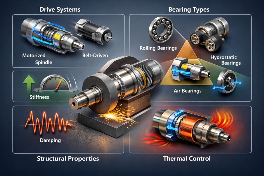
2. Spindle Drive Systems: Power and Efficiency
The drive system of a grinding spindle is more than just a means of transmitting rotational force; it is the starting point for determining the machine’s overall dynamic behavior and thermal stability. The choice between Motorized (Built-in) and Belt-driven configurations involves distinct engineering trade-offs in power transmission efficiency, vibration isolation, and thermal management—all of which directly impact production throughput.
Motorized (Integral) Spindles
Preferred in modern high-speed CNC grinding, the motorized spindle features a rotor mounted directly onto the spindle shaft. By eliminating intermediate transmission elements, it achieves maximum power efficiency and high-response control without mechanical backlash. This compact design is essential for multi-axis machines or applications requiring complex geometric interpolations.
The primary engineering challenge, however, lies in thermal management. Heat generated by the stator during high-speed operation is conducted directly into the spindle housing and shaft, causing thermal drift. To mitigate this, high-precision spindles require sophisticated cooling jackets and thermal stabilization cycles, which increase both system complexity and initial capital expenditure.
[Image: Diagram of an integral motorized spindle showing cooling jacket flow and rotor/stator alignment]
Belt-Driven Spindles
The belt-driven configuration physically separates the motor—the primary heat source—from the spindle structure. This thermal isolation inherently limits the spindle’s thermal expansion, making it highly stable for long production runs. Furthermore, the belt acts as a natural damping element, filtering out high-frequency motor vibrations before they reach the grinding wheel, which is often beneficial for achieving superior surface finishes.
The downside is the side load imposed on the spindle bearings by belt tension, which can accelerate wear and reduce bearing life. Additionally, belt slip or elasticity can limit precise speed control at very high RPMs, and regular maintenance is required to monitor belt integrity and tension levels.
The Power Axiom: “Selecting a drive system is a compromise between control and isolation. Motorized spindles offer the pinnacle of speed and responsiveness, while belt-driven systems provide a stable thermal environment for high-precision finishing.”
3. Bearing Technologies: The Physics of Support
The bearing system is the most critical sub-component of the spindle, as it must maintain the axis of rotation under high-frequency grinding loads. The selection of bearing technology determines the spindle’s Static Stiffness, Dynamic Damping, and Thermal Signature. In modern grinding, three distinct technologies dominate the landscape, each serving a specific niche in the precision-productivity matrix.
Rolling Element Bearings: The Industry Standard
Utilizing high-precision ceramic or steel balls, rolling element bearings provide a highly rigid mechanical connection between the shaft and the housing. Their primary advantage is Predictable Stiffness and ease of integration. By adjusting the Preload, engineers can fine-tune the balance between rigidity and heat generation. However, because they rely on point contact, they possess lower damping compared to fluid-film bearings, making them more susceptible to high-frequency chatter in certain resonant zones.
Hydrostatic Bearings: Infinite Life & Damping
In hydrostatic systems, the shaft is “floated” on a pressurized film of oil. This eliminates metal-to-metal contact, theoretically providing infinite bearing life. The oil film acts as a massive Squeeze-Film Damper, absorbing process vibrations and preventing them from reaching the workpiece. This makes hydrostatic spindles ideal for heavy-duty applications like roll grinding or large-scale component manufacturing where high material removal rates (MRR) and superior finishes must coexist.
Air (Aerostatic) Bearings: The Nano-Precision Frontier
Air bearings replace oil with pressurized air. Since air has significantly lower viscosity, these spindles can achieve extremely high RPMs (exceeding 100,000) with nearly zero heat generation from friction. They offer the lowest possible Non-Repetitive Run-out (NRR), making them the gold standard for semiconductor wafer grinding and lens manufacturing. The trade-off is Load Capacity; air is compressible, meaning these spindles cannot withstand the heavy side-loads typical of conventional vitrified wheel grinding.
The Bearing Axiom: “In grinding, the bearing is the filter. Rolling elements provide a stiff path, fluids provide a damped path, and air provides a friction-free path. The choice depends entirely on whether you are fighting deflection, vibration, or surface roughness.”
4. Structural Integrity: Stiffness and Damping
In precision grinding, the spindle is subjected to continuous normal forces (Fn) that attempt to deflect the wheel away from the workpiece. The spindle’s Structural Integrity is defined by its ability to maintain the commanded position of the wheel edge under these loads. This is a function of two distinct but related properties: Static Stiffness and Dynamic Damping.
Static Stiffness (kstatic) and Dimensional Accuracy
Static stiffness refers to the spindle’s resistance to a constant load. If a spindle has low static stiffness, the grinding forces will cause the shaft to flex, leading to a “compliance error.” This results in the finished part being larger than intended or having poor taper control. In high-stiffness spindles, the deflection (δ) is minimized according to the relationship δ = F / k. For processes requiring high Cpk, a static stiffness exceeding 100-200 N/μm is often required.
Dynamic Stiffness and Chatter Suppression
While static stiffness handles constant force, Dynamic Stiffness handles vibrations. Grinding is a regenerative process where a small vibration can create a “wave” on the wheel or workpiece, which then amplifies further vibrations. This is known as Chatter.
The dynamic stiffness is determined by the spindle’s Damping Ratio (ζ). Fluid-film bearings (hydrostatic) naturally provide higher damping than rolling element bearings. A spindle with high damping can “absorb” the energy of these vibrations, allowing for higher material removal rates (MRR) without sacrificing surface finish.
The Role of Bearing Preload
For rolling element spindles, stiffness is primarily controlled through Bearing Preload. Increasing the preload removes internal clearances and increases the contact area between the balls and races, effectively raising the k-value. However, engineers must balance this against the “Thermal Penalty”—excessive preload leads to higher friction and heat, which can cause the spindle to fail prematurely.
The Structural Axiom: “Stiffness wins the battle for size, but damping wins the battle for finish. A spindle must be stiff enough to hold the micron, but damped enough to ignore the vibration.”
5. Thermal Dynamics and Elongation Control
As a spindle operates, internal energy losses in the motor and friction in the bearings generate heat. This thermal energy causes the spindle shaft and housing to expand, a phenomenon known as Thermal Drift. In precision grinding, where axial tolerances are often less than 5μm, even a slight temperature rise can cause the spindle to grow by 10 to 50μm, leading to catastrophic dimensional errors and a loss of process capability (Cpk).
The Mechanism of Axial Elongation
The spindle shaft typically expands forward from its “fixed” bearing position. Because most grinding spindles use a Fixed-Floating bearing arrangement to allow for thermal growth, the shaft elongates toward the grinding wheel. If the machine’s control system does not account for this growth, the wheel will move closer to the workpiece than commanded, resulting in undersized parts or excessive depth of cut that may trigger Grinding Burn.
Active Cooling Strategies
To maintain Thermal Equilibrium, high-performance motorized spindles utilize an integrated Cooling Jacket. A chiller circulates temperature-controlled oil or water around the motor stator and the bearing seats. The goal is not just to keep the spindle cool, but to keep it at a Constant Temperature. Fluctuations in coolant temperature can be just as damaging to precision as the heat itself, causing “cycling” errors in the finished part dimensions.
Symmetric Design and Compensation
Advanced spindle manufacturers employ Symmetric Structural Design to ensure that any thermal growth occurs in a predictable, linear direction that can be easily compensated for by the CNC. Additionally, thermal sensors embedded in the spindle housing can provide real-time data to the controller, which then applies a “Software Offset” to the Z-axis to counteract the measured elongation in real-time.
The Thermal Axiom: “Heat is the enemy of the micron. In a precision spindle, we do not fight heat with strength; we fight it with stability, symmetry, and constant circulation.”
6. Application-Specific Selection Criteria
There is no “universal” spindle that excels in every grinding scenario. Selecting the correct unit requires an engineering audit of the Material Removal Rate (MRR), the wheel type, and the target surface topography. The spindle must be sized to operate within its “Performance Sweet Spot,” ensuring that the power-to-weight ratio and bearing stiffness are aligned with the dominant forces of the specific application.
High-Speed Micro Grinding: The Case for Air Bearings
In micro-grinding, such as semiconductor wafer thinning or lens fabrication, the grinding wheels are often very small in diameter. To maintain a productive Surface Speed (vs), the spindle must rotate at extremely high frequencies (60,000 to 120,000 RPM). At these speeds, rolling element bearings fail due to centrifugal forces and heat. Air Bearing Spindles are the logical choice here, providing the zero-friction environment necessary for nano-level surface finishes.
Heavy-Duty Roll Grinding: The Power of Hydrostatics
In contrast, roll grinding for the steel or paper industry involves massive wheels (up to 1 meter in diameter) and high normal forces. The priority here is Vibration Damping and Load Capacity. A Hydrostatic Spindle is preferred because its pressurized oil film can support tons of force without metal-to-metal contact, while its inherent damping prevents the large-scale regenerative chatter that can occur when grinding hardened rolls.
Abrasive Selection and Power Requirements
The choice of abrasive also dictates spindle power. Superabrasives (CBN/Diamond) often require lower tangential forces but higher spindle speeds and greater machine rigidity compared to conventional Al2O3 wheels. When selecting a spindle for CBN, the Torque-Speed Curve must be carefully reviewed to ensure that the spindle provides its peak power at the specific surface speed required for the abrasive to act efficiently.
The Application Axiom: “Matching a spindle to an application is about energy balance. Too much power for a small wheel leads to vibration; too little power for a large wheel leads to stall and wheel glazing. The spindle must be the perfect mechanical bridge between the motor and the material.”
7. Maintenance, Reliability, and TCO
A high-performance spindle is a significant investment. Beyond the initial purchase price, the Total Cost of Ownership (TCO) is heavily influenced by reliability and the cost of unplanned downtime. In a high-volume production environment, a spindle failure is not just a repair cost; it is a halt in the entire value stream. Therefore, selecting a spindle requires evaluating its Mean Time Between Failures (MTBF) and the accessibility of its maintenance components.
Predictive Maintenance: The Role of Sensors
Modern precision spindles are no longer “black boxes.” Integrated Condition Monitoring Systems utilize vibration accelerometers and thermal sensors to track the health of the bearings in real-time. By monitoring the frequency spectrum of the spindle, engineers can detect the early onset of bearing fatigue or misalignment before it results in part scrappage. This shift from reactive to Predictive Maintenance is the primary driver for reducing OPEX in smart factories.
The Economic Contrast: Air vs. Oil vs. Grease
The lubrication method dictates a large portion of the TCO. Grease-lubricated rolling bearings have the lowest maintenance cost but are limited in speed. Oil-Air lubrication allows for higher speeds but requires a continuous supply of expensive filtered air and precise oil dosing. Hydrostatic systems, while having nearly infinite bearing life, require massive energy to run the high-pressure hydraulic pumps and chillers. Engineers must calculate whether the increased process stability of a fluid-film spindle justifies the higher utility costs over a 5-to-10-year lifecycle.
Repairability and Serviceability
Belt-driven spindles generally offer higher serviceability, as belts and external motors can be replaced by on-site technicians. Motorized (Built-in) spindles often require factory-level refurbishment, which can take weeks. For mission-critical operations, the TCO strategy must include either a “Spare Spindle” inventory or a guaranteed service contract with the manufacturer to minimize the impact of the Mean Time to Repair (MTTR).
The Reliability Axiom: “The cheapest spindle to buy is rarely the cheapest spindle to own. True manufacturing economy is found in the intersection of low utility costs and the elimination of unplanned spindle changes.”
8. Conclusion: Strategic Procurement Checklist
Selecting a precision grinding spindle is a high-stakes engineering decision that balances the immediate needs of geometric accuracy with the long-term demands of process stability and cost management. As we have explored, the ideal spindle is not the one with the highest specifications, but the one whose physical attributes—stiffness, damping, and thermal response—best align with the specific material removal mechanism of the application.
Final Engineering Synthesis
For high-volume, high-precision manufacturing, the trend is moving toward Motorized Spindles with active thermal compensation. However, for extreme precision and low-load scenarios, Air Bearings remain the only viable frontier. Conversely, in the world of heavy industrial grinding, the high-damping characteristics of Hydrostatic systems provide a level of chatter resistance that rolling elements cannot match. The modern engineer must act as a systems integrator, ensuring the spindle’s “Mechanical Soul” matches the machine’s “Digital Brain.”
The Strategic Procurement Checklist
- Static Stiffness Check: Does the spindle k-value prevent mean-shift errors under maximum normal force (Fn)?
- Thermal Management: Is there a refrigerated cooling jacket for motorized units, or a thermal isolation strategy for belt drives?
- Rotational Fidelity: Is the non-repetitive run-out (NRR) compatible with the target surface finish (Ra)?
- Dynamic Damping: Is the damping ratio sufficient to suppress regenerative chatter for the intended material removal rate?
- TCO Analysis: Have you accounted for utility costs (pumps/compressors) and factory-refurbishment lead times?
Final Engineering Proclamation: “A precision spindle is a commitment to a specific physical philosophy. Whether you choose the rigid path of rolling elements or the floated path of fluids, the success of your grinding process depends on how well you manage the inevitable intersection of heat, force, and vibration.”
Internal Technical Deep-Dive
For more detailed insights into process control and mechanics, please refer to the following internal resources:
References & Internal Technical Resources
Primary Engineering References
- • Altintas, Y. (2012). Manufacturing Automation: Metal Cutting Mechanics, Machine Tool Vibrations, and CNC Design. Cambridge University Press. (Modeling of spindle dynamics and bearing stiffness).
- • Rowe, W. B. (2009). Principles of Modern Grinding Technology. William Andrew. (Analysis of thermal drift and fluid-film bearing systems).
- • Ganesan, H. (2018). High Speed Spindles for Machine Tools. DEStech Publications. (Thermal stability and active cooling strategies in motorized spindles).
Internal Technical Deep-Dive
For further exploration of the engineering principles discussed in this report, please refer to the following internal technical modules: