1. Introduction: The Definition of Grinding Efficiency
In the competitive landscape of modern manufacturing, Grinding Efficiency is often misunderstood as simply “running the machine faster.” However, true industrial efficiency is the optimization of the Material Removal Rate (MRR) while simultaneously maintaining part quality and maximizing tool life. It is a multi-dimensional challenge where increasing productivity in one area can lead to catastrophic failure—such as thermal damage or chatter—in another.
In real shops, I’ve seen “run it faster” become the default answer when a deadline tightens. The problem is that grinding rarely fails loudly at first—it fails quietly, one slightly hotter part, one small chatter band, one extra dress cycle… until the scrap bin starts filling.
The Efficiency Equation: Quality vs. Throughput
To improve efficiency deterministically, we must view the grinding process as a system of energy conversion. Efficiency is maximized when the Specific Energy (u)—the energy required to remove a unit volume of material—is minimized. When the process is inefficient, excess energy is converted into heat, leading to “grinding burn” and rapid wheel wear, which ultimately forces a reduction in speed and increases total cycle time.
The Three Pillars of Efficiency Optimization
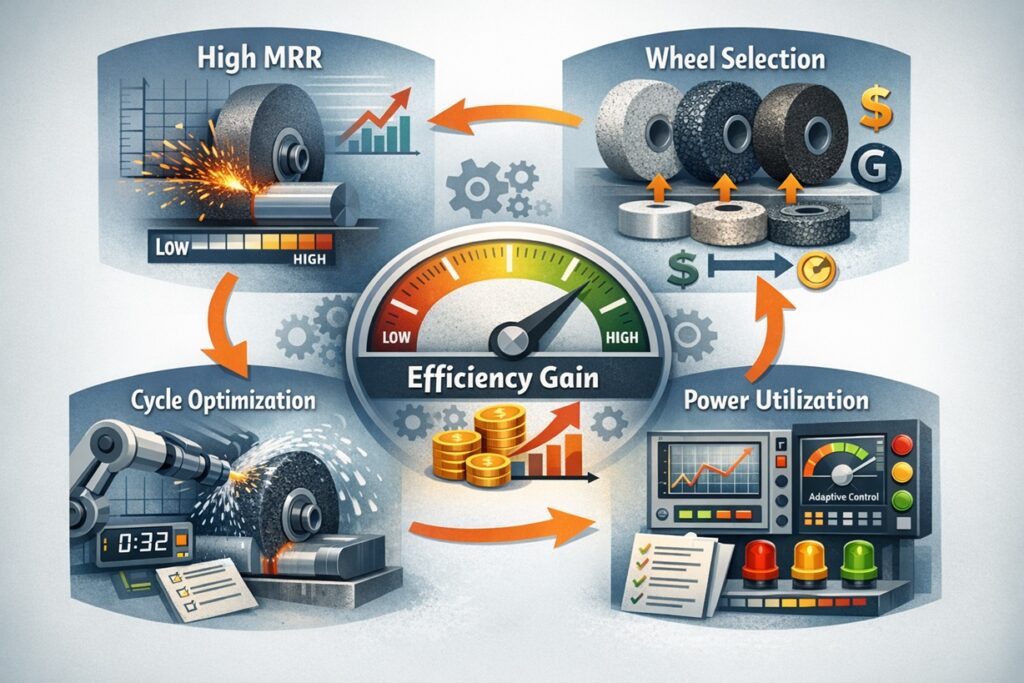
Improving efficiency requires a strategic focus on three variables that have the highest impact on the bottom line:
- • Volumetric Consistency: Maintaining a high Q’ω (Specific MRR) without triggering thermal instability.
- • Utilization of “Non-Cutting” Time: Reducing air-grinding and sensor-lag to ensure the wheel is always in contact with the material during the active cycle.
- • G-Ratio Maximization: Increasing the volume of material removed per unit of wheel wear to minimize downtime for dressing and wheel changes.
In the following sections, we will dissect the variables that actually move the needle in production. We begin with the most critical diagnostic value for any grinding engineer: the Specific Material Removal Rate. This single number reveals the true “intensity” of your process.
2. The Golden Variable: Specific Material Removal Rate (Q′w)
To improve what you cannot measure is impossible. In grinding, the absolute Material Removal Rate (MRR) can be misleading because it depends on the width of the part. To normalize efficiency across different machines and components, we use the Specific Material Removal Rate (Q′w). This variable represents the volume of material removed per second, per millimeter of grinding width.
The Calculus of Throughput
The formula for Q′w is deceptively simple but profoundly impactful:
Q′w = vw × ae
Where vw is the workpiece speed and ae is the depth of cut. By focusing on Q′w, an engineer can determine the “aggressiveness” of the cycle. If Q′w is too low, the process is under-utilized; if it is too high, the spindle may stall or the part may burn.
When I walk up to a machine for the first time, I don’t ask for a long story—I ask for two numbers: the current Q′w and the spindle load trend. Those two usually tell me whether we’re cutting, rubbing, or quietly heading toward a burn problem.
Benchmarking Industrial Efficiency
Efficiency is relative to the material and the machine’s capability. By comparing your current Q′w against industrial benchmarks, you can identify if your process has “headroom” for improvement. For instance, shifting a process from 2 mm³/mm·s to 5 mm³/mm·s more than doubles productivity, provided the cooling and dressing strategies can keep up.
The $Q′w$ Safety Ceiling
Every setup has a Critical Q′w beyond which the fluid can no longer evacuate the heat. Increasing efficiency means pushing this ceiling higher by optimizing wheel porosity and coolant pressure. Once the ceiling is raised, you can safely increase vw or ae to reach the new productivity target.
Understanding Q′w gives us the target, but we need a mechanism to reach it without destroying the part. In the next section, we explore Strategy 1: Maximizing Aggressiveness via Chip Thickness (hcu) to see how we can manipulate the physics of the cut.
3. Strategy 1: Maximizing Aggressiveness via Chip Thickness (hcu)
To truly increase efficiency, we must manipulate the Undeformed Chip Thickness (hcu). In grinding, material removal efficiency is highest when the grains are “biting” deeply into the material rather than rubbing against it. By increasing the chip thickness, we shift the process energy from friction and plowing toward effective cutting, which lowers the Specific Energy (u) of the process.
The Efficiency Paradox: Higher Speed vs. Heavier Cut
A common mistake in efficiency optimization is focusing solely on wheel speed (vs). While high vs improves finish, it actually decreases hcu, making the wheel act “harder” and increasing the risk of glazing and thermal damage. To improve efficiency, we often do the opposite: we increase the Workpiece Velocity (vw) or the Depth of Cut (ae).
Calculating the Aggressiveness Factor
Efficiency is driven by the Aggressiveness of the cut. For a given Q′w, a heavier cut with fewer active grains is more energy-efficient than a light cut with many grains. The simplified relationship for chip thickness is:
hcu ∝ (vw / vs) × √(ae / de)
By increasing the vw / vs ratio, we force each abrasive grain to remove more material, reducing the total friction area and heat generation per unit volume.
The “Efficiency Zone” Limits
While increasing hcu improves efficiency, it also increases the Normal Force (Fn) on each grain. If pushed too far, the wheel will wear prematurely (fracture wear), leading to a poor G-ratio. The goal is to find the “sweet spot” where the MRR is maximized but the grain remains stable.
Manipulating the kinematics is one half of the efficiency puzzle; the other half is the tool itself. In the next section, we look at Strategy 2: Wheel Selection as a Multiplier to see how wheel structure can enable these aggressive parameters.
4. Strategy 2: Wheel Selection as a Multiplier
Even the most optimized kinematic parameters will fail if the grinding wheel cannot support the increased load. In the quest for efficiency, the wheel acts as a Force and Heat Multiplier. Selecting a wheel with the right Induced Porosity and abrasive type is what allows an engineer to push the Q′w beyond standard limits without risking thermal burn or workpiece rejection.
High-Porosity Structures for Cool Cutting
Efficiency is often bottlenecked by the wheel’s ability to transport coolant and evacuate chips. Highly Porous (Induced Pore) wheels provide large “pockets” that carry fluid directly into the contact zone and provide space for long, efficient chips. This structure lowers the friction-induced Tangential Force (Ft), which is the primary source of heat. By using a porous wheel, you can often increase the depth of cut by 20–30% without an increase in spindle power.
Superabrasives (CBN) and the Economic Shift
While conventional Alumina wheels are cost-effective, Cubic Boron Nitride (CBN) wheels are the ultimate efficiency multipliers for steel. CBN’s high thermal conductivity allows it to “wick” heat away from the workpiece, and its extreme hardness maintains wheel profile 100 to 500 times longer than Alumina. This results in a massive increase in the G-ratio, significantly reducing downtime for dressing.
The Logic of the G-Ratio
Efficiency is lost every time the wheel stops spinning for maintenance. By selecting a wheel that yields a higher G-ratio (Volume of material removed / Volume of wheel worn), you maximize the machine’s “Green Light” time. In high-volume production, a wheel that lasts twice as long is often more valuable than a wheel that cuts 10% faster.
Having the right tool and parameters is essential, but efficiency is also hidden in the spaces between the cuts. In the next section, we look at Strategy 3: Eliminating Non-Cutting Time to recover the “lost” minutes of the grinding cycle.
5. Strategy 3: Eliminating Non-Cutting Time (The Hidden Loss)
Industrial efficiency is not only about the speed of material removal but also about the ratio of Value-Added Time to total cycle time. A significant portion of productivity is often lost to “Air-Grinding”—the time the wheel spends moving through space before making contact. Eliminating these hidden losses is the fastest way to improve efficiency without changing a single cutting parameter.
This is the part most people underestimate because it doesn’t look “technical.” But a few seconds of air-grinding on every part is the kind of loss that never shows up in one cycle—only in the monthly output report. That’s why the quickest wins often come from motion, timing, and measurement rather than pushing the wheel harder.
Gap Elimination and Acoustic Emission (AE)
In traditional setups, operators use a large safety margin for the Rapid-to-Grind transition point to avoid “crashing” the wheel. This creates seconds of wasted motion per part. By implementing Acoustic Emission (AE) Sensors, the machine can detect the exact micro-second the wheel touches the workpiece. This allows for a “Gap Elimination” strategy where the wheel approaches at high speed and switches to grinding feed only upon actual contact.
Optimization of the Dressing Cycle
Dressing is necessary but non-productive. Efficiency improves when Adaptive Dressing is used instead of time-based dressing. By monitoring the spindle load, the system can trigger a dressing cycle only when the wheel is actually dull (indicated by a rise in power), rather than after a fixed number of parts. This prevents over-dressing, extending wheel life and increasing machine uptime.
Reducing “Approach” Distances
In cylindrical or surface grinding, the “over-travel” distance at the end of each stroke is often set too wide. Reducing the over-travel to the minimum required for the wheel to clear the part can shave 5–10% off the total cycle time in long-stroke operations.
Recovering these seconds allows the machine to operate closer to its theoretical maximum removal rate. However, to sustain these gains, we must also ensure we are using the full capacity of the machine’s spindle. In the next section, we look at Strategy 4: Power Limit Utilization & Spindle Load.
6. Strategy 4: Power Limit Utilization & Spindle Load
The ultimate ceiling for grinding efficiency is the Available Spindle Power (Ps). Many industrial processes operate at only 40–50% of the machine’s rated capacity to avoid risk. However, deterministic efficiency requires utilizing the spindle load as a real-time feedback loop. By pushing the process closer to the machine’s power limit, you maximize the Q′w while ensuring the system remains within a stable operating window.
Monitoring Specific Grinding Power (u)
Efficiency is measured by the Specific Energy (u), which is the power consumed per unit volume of material removed.
u = Pnet / (vw × ae × b)
If the spindle load increases while the MRR remains constant, it indicates the wheel is dulling or glazing. High-efficiency shops use Adaptive Control systems that automatically adjust the feed rate (vf) to maintain a constant spindle load, ensuring the machine always runs at peak capacity regardless of wheel condition.
The “Sweet Spot” of Spindle Utilization
Operating at 70–80% of rated spindle power is typically the “sweet spot” for high-efficiency grinding. This provides a safety buffer for transient force spikes while ensuring the abrasive grains are operating in their self-sharpening regime. When power utilization is too low, the grains do not fracture as intended, leading to “rubbing” and an inefficient increase in specific energy.
Machine Rigidity and Dynamic Power
It is important to note that spindle power is limited by the Dynamic Stiffness of the machine. High-efficiency grinding requires a rigid path between the wheel and workhead. If the machine begins to vibrate before reaching the power limit, the efficiency is “stiffness-limited” rather than “power-limited,” requiring a shift in dressing or wheel grade to lower the forces.
Pushing the boundaries of power and MRR carries a major risk: thermal overload. To sustain high efficiency, we must prevent the “Burn Trap.” In the next section, we look at Efficiency vs. Stability: Avoiding the “Burn” Trap.
7. Efficiency vs. Stability: Avoiding the “Burn” Trap
As the Material Removal Rate (Q′w) increases, so does the heat flux entering the workpiece. In the pursuit of efficiency, engineers often fall into the “Burn Trap”—a state where productivity gains are negated by high scrap rates due to thermal damage. To achieve sustainable high efficiency, the process must remain below the Burn Threshold, where the heat generated exceeds the cooling capacity of the system.
The Critical Heat Flux (qc)
Efficiency is limited by the boiling point of the grinding fluid. Once the fluid in the contact zone reaches its boiling temperature (film boiling), its ability to remove heat drops by over 90%, causing an instantaneous spike in surface temperature. Preventing this requires a High-Pressure Coolant Strategy where the jet velocity (vj) matches the wheel speed (vs), ensuring the fluid “washes” the contact zone rather than being deflected by the air barrier.
Chatter: The Mechanical Stability Barrier
Beyond thermal limits, efficiency is often capped by Regenerative Chatter. As vw increases to improve throughput, the system may hit a resonant frequency. To stay in the high-efficiency zone, engineers must use Stability Lobe Diagrams to identify “sweet spots” of spindle speed and feed rate that suppress vibration. Using a wheel with a slightly softer grade or high damping can also shift the stability boundary higher.
To synthesize these strategies into a practical result, we must look at a real-world implementation. In the final section, we present a Case Study: 30% Productivity Increase Roadmap, demonstrating how these variables move the needle in a production environment.
8. Case Study: 30% Productivity Increase Roadmap
To demonstrate the practical application of these variables, we examine a optimization project for a high-volume automotive component manufacturer. The objective was to increase throughput by 30% on a hardened steel shaft grinding line without investing in new machinery. By shifting the focus from “speed” to Deterministic Efficiency, the following roadmap was implemented.
The Baseline Audit
The initial process was running at a Q′w of 2.2 mm³/mm·s with a cycle time of 45 seconds. Spindle load was only at 35%, and significant time was lost to air-grinding and conservative dressing intervals.
Step-by-Step Optimization Sequence
- Phase 1: Kinematic Aggressiveness. Increased work speed (vw) by 20% and slightly reduced wheel speed (vs). This increased the chip thickness (hcu), moving the process out of the “rubbing” zone.
- Phase 2: Gap Elimination. Integrated AE sensors to eliminate 3 seconds of air-grinding per cycle.
- Phase 3: Wheel Structure. Switched from a standard Alumina wheel to a high-porosity ceramic abrasive, allowing for a 15% increase in depth of cut (ae).
Summary: Efficiency is a Choice
Efficiency is not a byproduct of modern machinery; it is the result of an engineer choosing to manage the variables that “actually matter.” By focusing on Q′w, hcu, and spindle utilization, any facility can unlock hidden capacity. As this case study shows, a 30% productivity gain is often already present in your machine—you simply need the scientific framework to release it.
Final Efficiency Takeaway
“Speed is a consequence of physics. When you optimize the chip thickness and the thermal evacuation, higher efficiency becomes the natural state of the process.”
References & Further Reading
Technical Publications & Industrial Standards
- • Stephen Malkin & Changsheng Guo (2008). Grinding Technology: Theory and Applications of Machining with Abrasives. (Focus: Specific energy models and Material Removal Rate optimization).
- • Tönshoff, H. K., & Friemuth, T. (2002). Process Monitoring in Grinding. CIRP Annals. (Focus: Sensor-based efficiency and adaptive control strategies).
- • Jeffrey Badger (2013). The Book of Grinding. (Focus: Practical wheel selection and high-efficiency cycle design).
- • Marinescu, I. D. (2007). Handbook of Machining with Grinding Wheels. (Focus: Comparative analysis of MRR across different abrasive types).
Curated Internal Resources: Efficiency Optimization Series
To further reduce cycle times and maximize your machine’s potential, we recommend the following deep-dives:
CYCLE OPTIMIZATION:
Surface Grinding Process Optimization: Strategies for Variable Control and Productivity Enhancement
UPTIME MAXIMIZATION:
Dressing and Truing Mechanisms: Principles of Wheel Regeneration and Surface Generation
FORCE DYNAMICS:
Mechanics of Grinding Forces: Understanding Tangential/Normal Forces and Force Ratio
Industrial Efficiency Research Institutions
- Machine Tool Laboratory (WZL) at RWTH Aachen: Global leader in high-performance grinding and industrial process monitoring.
- The Grinding Institute: Specialized in technical training for reducing cycle times and optimizing specific removal rates.
© 2026 Advanced Machining Intelligence | Strategic Resource for Process Optimization and Industrial Efficiency