1. Introduction: The Fragile Nature of Hardness
In the hierarchy of manufacturing, Hardened Steel represents a peak of mechanical performance, offering the wear resistance and structural rigidity necessary for high-precision tools, bearings, and dies. However, this high hardness comes at a cost: increased thermal sensitivity and brittle behavior. When steel is hardened—typically through quenching and tempering—it reaches a metastable martensitic state that is exceptionally unforgiving during the grinding process.
The Grindability Conflict
As the Rockwell hardness (HRC) of a material increases, its Grindability Index generally decreases. Hardened steels require high Specific Grinding Energy (u) to achieve material removal. This energy is largely converted into heat at the tool-workpiece interface. Unlike annealed steels, where a portion of the heat is carried away by the chips, the high strength of hardened steel restricts chip deformation, forcing a higher percentage of thermal energy to conduct directly into the surface layer.
The Risk of “Latent” Defects
The most dangerous aspect of grinding hardened steel is that catastrophic damage is often invisible. A component may appear dimensionally perfect and exhibit a mirror-like finish, yet harbor Tensile Residual Stresses or micro-cracks that lead to premature failure under operational loads. Because these steels have low fracture toughness, any thermal anomaly during grinding acts as a catalyst for immediate or delayed surface degradation.
- • Thermal Fragility: Small variations in temperature (as low as 200°C to 300°C) can cause localized tempering and loss of hardness.
- • Brittle Fracture: High-hardness surfaces lack the ductility to absorb the mechanical “shocks” of an aggressive grinding cycle.
- • Structural Sensitivity: The martensitic structure is susceptible to phase transformations if the grinding temperature crosses the Ac1 line.
To solve these problems, we must first understand the “silent” metallurgical transformations occurring within the steel. In the next section, we examine the Thermal Damage Mechanism: From Tempering to Re-hardening to identify the temperatures that lead to catastrophic surface failure.
In real production, hardened steel grinding rarely fails in a dramatic way at first—it usually starts with subtle changes that are easy to dismiss as “normal variation.” This guide is organized around those small warning signs so the process can be corrected before the damage becomes permanent.
2. Thermal Damage Mechanism: From Tempering to Re-hardening
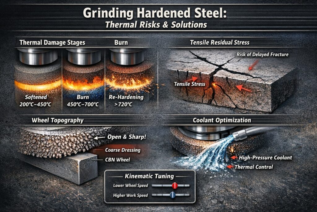
Thermal damage in hardened steel grinding extends far beyond surface discoloration; it fundamentally alters the material’s Metallurgical State. As the temperature at the grinding interface rises, the steel undergoes three critical stages: Tempering, Oxidation, and finally, Re-hardening. Each phase introduces distinct changes to the hardness and mechanical properties of the component.
Stage 1: Grinding Tempering (Localized Softening)
When the grinding temperature exceeds the material’s original tempering temperature (typically between 200°C and 500°C), Over-tempering occurs. In this stage, carbon atoms precipitate out of the martensitic structure, causing a localized reduction in hardness. While the part may show no visual change, its wear resistance is severely compromised, leading to premature failure in high-friction environments.
Stage 2: Grinding Burn (Oxidation Layers)
As the temperature continues to rise toward 400°C–700°C, iron atoms on the surface react with oxygen to form an oxide film. This is known as Grinding Burn. The color of the burn—ranging from straw to brown or deep blue—is determined by the thickness of the oxide layer. Visual burn is a definitive warning sign that significant thermal energy has penetrated into the substrate, likely causing subsurface tempering.
Stage 3: Re-hardening & White Layer Formation
The most severe damage occurs when temperatures surpass the lower transformation point (Ac1, approximately 720°C). At this peak, the surface layer becomes austenitic and is instantaneously quenched by the coolant, forming Untempered Martensite. This is the White Layer. Although extremely hard, it is exceptionally brittle and prone to micro-cracking. Crucially, a softened, over-tempered zone always exists immediately beneath this brittle layer, creating a profound structural instability.
These metallurgical shifts do not just change the surface properties; they create a massive imbalance of internal forces. Having analyzed the thermal triggers, we can now move to the mechanical consequences in Section 3: The Invisible Enemy: Tensile Residual Stress & Grinding Cracks.
3. The Invisible Enemy: Tensile Residual Stress & Grinding Cracks
In hardened steel, the most devastating “invisible” defect is Tensile Residual Stress. During the grinding process, the surface layer expands rapidly due to localized heat. However, the cool, rigid bulk of the material resists this expansion. When the grinding wheel passes and the surface is quenched by coolant, it attempts to contract. This thermal contraction is constrained by the bulk, leaving the surface in a state of permanent tension that “pulls” the material apart at the atomic level.
The Threshold of Fracture: Grinding Cracks
Hardened steels possess high strength but very low Fracture Toughness (KIC). When the magnitude of the tensile residual stress exceeds the material’s local yield strength, the surface ruptures. These Grinding Cracks typically form perpendicular to the grinding direction and are often extremely shallow—initially only a few microns deep—making them undetectable without fluorescent penetrant or magnetic particle inspection.
Delayed Cracking and Hydrogen Embrittlement
A critical phenomenon in high-hardness steel (above 55 HRC) is Delayed Cracking. A part may pass inspection immediately after grinding, only to develop cracks hours or days later. This is often caused by the slow migration of residual stresses or the presence of hydrogen from the grinding fluid (Hydrogen Embrittlement). The high tensile stress acts as a continuous driving force, slowly pulling the grain boundaries apart until a macro-crack appears.
The Mechanics of Stress Suppression
To eliminate tensile stress, the Mechanical Removal Action must dominate the Thermal Expansion. This requires a wheel that stays sharp and open. If the wheel surface becomes “glazed,” the cutting edges no longer penetrate the material, leading to massive heat generation and a total shift toward tensile failure.
Controlling the wheel’s surface state is the most effective way to manage these stresses. In the next section, we look at Section 4: Wheel Topography Control: Preventing Glazing on Hard Surfaces.
4. Wheel Topography Control: Preventing Glazing on Hard Surfaces
When grinding hardened steel, the abrasive grains encounter extreme mechanical resistance. If the wheel bond is too “hard” or the dressing is too fine, the grains do not fracture to reveal new sharp edges. Instead, they develop Wear Flats. This phenomenon, known as Glazing, turns the grinding wheel into a friction disk, generating massive heat without effective material removal. Controlling the Wheel Topography is the primary defense against this thermal trap.
The Mechanism of Self-Sharpening
Effective grinding of hardened surfaces relies on Micro-fracturing. A properly selected wheel must have a bond strength that allows grains to fracture under the high cutting forces required for hardened steel. This “self-sharpening” action keeps the wheel Open and Aggressive, ensuring that the grains penetrate the martensitic structure rather than sliding over it and generating friction.
Dressing Overlap Ratio (Ud) for Hardened Steel
The dressing process defines the initial topography of the wheel. For hardened steel, a Coarse Dressing strategy is often superior to a fine one. By reducing the Overlap Ratio (Ud)—the number of times the dresser passes over a single point on the wheel—we create a “sharper” wheel surface with higher Chip Storage Volume. This allows for better coolant transport and prevents the wheel from “smearing” the metal.
Vitrified CBN vs. Induced Porosity
For high-volume grinding of hardened components, Vitrified CBN wheels are the ultimate solution. Their extreme hardness prevents the formation of wear flats, while their high thermal conductivity helps “wick” heat away from the workpiece. If using conventional Alumina, an Induced Pore structure is necessary to provide the pockets required to clear long, hard chips and prevent the wheel from Loading.
While topography ensures the wheel’s ability to cut, the actual motion of the machine must be tuned to keep temperatures low. In the next section, we explore Section 5: Kinematic Solutions: Parameter Tuning for Hardened Surfaces.
5. Kinematic Solutions: Parameter Tuning for Hardened Surfaces
Once the wheel topography is optimized, the next line of defense against thermal damage is the Kinematic Setup. In hardened steel grinding, the goal is to shift the energy away from the workpiece and into the chips. This is achieved by manipulating the relationship between wheel speed (vs) and work speed (vw) to control the Uncut Chip Thickness (hcu).
The Paradox of Wheel Speed (vs)
While increasing vs is a common way to improve surface finish, it is often counterproductive when grinding hardened steel. High wheel speeds reduce the chip thickness per grain, causing the abrasive to “rub” rather than “cut.” This rubbing generates massive friction without removing material. By reducing vs slightly (e.g., from 35 m/s down to 25 m/s), each grain is forced to take a deeper bite, which increases the mechanical removal efficiency and reduces the specific energy (u).
Note: the “safe” adjustment range depends strongly on wheel specification, machine power/stiffness, dressing condition, and coolant delivery—so the numbers should be treated as a starting reference, not a universal rule.
Increasing Work Speed (vw) for Thermal Evacuation
One of the most effective ways to prevent grinding burn is to increase the workpiece speed. A higher vw reduces the “dwell time”—the amount of time any single point on the workpiece is exposed to the heat of the grinding zone. This prevents the cumulative heat buildup that leads to tempering or re-hardening. When combined with a lower vs, this “aggressive” kinematic approach creates larger chips that carry more thermal energy away from the part.
The Concept of Energy Partitioning
In any grinding operation, the total energy is partitioned between the wheel, the chips, and the workpiece. By tuning the kinematics to produce larger, thicker chips, we maximize the percentage of energy leaving with the swarf. In hardened steel, where the window for error is narrow, this shift in energy partitioning is often the difference between a successful batch and a complete loss of surface integrity.
However, kinematics alone cannot solve all thermal problems. The final temperature at the surface is heavily dependent on how effectively the heat is removed by the fluid. In the next section, we examine Section 6: Coolant Optimization: Preventing Thermal Shock.
6. Coolant Optimization: Preventing Thermal Shock
In hardened steel grinding, the role of the coolant shifts from simple “heat removal” to a sophisticated Thermal Management System. Because these materials are highly sensitive to temperature gradients, the application of coolant must be precise. Inconsistent cooling can lead to Thermal Shock—a rapid contraction of the surface that triggers immediate micro-cracking in brittle martensitic structures.
Lubricity vs. Convection: The Oil vs. Water Debate
The choice between Neat Oil and Water-miscible fluids (soluble oils) depends on the grinding intensity. Neat oils offer superior Lubricity, which reduces the friction coefficient between the grain and the hardened surface, thereby preventing heat at the source. Water-based fluids, however, have a higher Convective Cooling Capacity. For high-HRC steels, neat oil is often preferred to keep the “Specific Energy” low, provided the delivery system can handle the fire risk.
Nozzle Placement and the “Nip” Engagement
For hardened steel, the coolant must reach the Nip (the entry point of the contact zone). If the coolant is applied too late or at a pressure lower than the centrifugal air barrier of the wheel, the surface will undergo “Dry Grinding” for a fraction of a second, followed by an immediate “Quench” from the fluid. This cycle is the primary cause of Check Cracks (lattice-like crack patterns) on hardened tools.
Preventing “Fluid Starvation”
Fluid starvation occurs when the abrasive wheel acts as a pump, throwing coolant away from the contact zone. Using a Scraper Plate or a secondary “Cleaning Nozzle” can break this air envelope, ensuring a flooded contact zone. In hardened steel, consistent fluid presence is the only way to avoid the “Flash Temperatures” that trigger Stage 3 re-hardening (White Layer).
Even with perfect cooling, some stress is unavoidable. To ensure a part is truly flight-ready or tool-ready, post-processing is required. In the next section, we examine Section 7: Post-Grinding Treatments: Stress Relief & Inspection.
7. Post-Grinding Treatments: Stress Relief & Inspection
Because the thermal and mechanical loads of grinding can disrupt the delicate balance of a hardened martensitic structure, the process does not end when the machine stops. To guarantee the reliability of high-HRC components, manufacturers must implement Post-Grinding Protocols designed to stabilize the material and verify that no “latent” defects—such as subsurface burns or tensile stresses—are present.
Stress Relief Tempering (Baking)
Even a well-controlled grinding process induces some level of residual stress. For critical hardened steel parts, a secondary Stress Relief Tempering (often called “baking”) is performed. By heating the part to a temperature slightly below its original tempering point (e.g., 150°C to 200°C), the atoms can rearrange to relax the Tensile Residual Stresses without losing bulk hardness. This step is vital for preventing “Delayed Cracking” in steels harder than 55 HRC.
Surface Integrity Inspection: Nital Etching
Visual inspection is notoriously unreliable for detecting grinding damage. The industry standard for verifying hardened steel is Nital Etching. By immersing the part in a mild nitric acid and alcohol solution, metallurgical anomalies are revealed through color contrast. Over-tempered areas appear dark gray/black, while re-hardened White Layers appear bright white.
In practice, Nital etching is often used as a quick “truth test” when you suspect burn or white layer on a critical surface, especially during setup changes or wheel dressing shifts. For high-volume lines, Barkhausen noise or eddy current methods are typically chosen when you need fast screening—then only the flagged parts move to deeper metallurgical inspection.
Non-Destructive Residual Stress Testing
For high-volume automotive and aerospace components, Barkhausen Noise Analysis is used for 100% in-line inspection. Because tensile stress and hardness loss change the way magnetic domains move within the steel, this non-destructive method can flag “burnt” parts in seconds, ensuring that only components with a compressive or neutral stress state move to final assembly.
Mastering the grinding of hardened steel requires a balance between aggressive kinetics and conservative thermal management. In the final section, we summarize the Section 8: Conclusion: Deterministic Control over Hardness.
8. Conclusion: Deterministic Control over Hardness
Grinding hardened steel is a high-precision balancing act where mechanical removal efficiency and metallurgical stability are in constant conflict. Success in this domain is not a matter of luck but of Deterministic Control. By understanding that every joule of energy introduced into the grinding zone must be accounted for—either carried away by the chips or suppressed through superior lubrication—engineers can prevent the thermal anomalies that compromise part life.
Summary of Strategy for Hardened Surfaces
To achieve a robust, “burn-free” process, the following pillars must be aligned:
- • Sharpness First: Prioritize an open wheel topography (Ud) to ensure clean grit penetration.
- • Kinematic Aggression: Increase work speed (vw) and optimize chip thickness (hcu) to evacuate heat.
- • Thermal Integrity: Match coolant jet velocity to wheel speed to prevent the air barrier from causing thermal shock.
- • Quantitative Verification: Use Nital etching and Barkhausen noise to confirm the absence of “Invisible Enemy” defects.
The Precision Perspective
“Hardness is a strength until it is mismanaged by heat. In the world of hardened steel, the grinder is not just a cutter, but a metallurgical architect.”
The transition from “reactive” grinding (fixing burns after they happen) to “proactive” grinding (designing cycles that cannot burn) marks the maturity of a manufacturing facility. As we continue this series, we will move from these material-specific challenges into the realm of Advanced Industrial Systems, ensuring that these principles are scalable across complex production environments.
References & Further Reading
Technical Publications & Industrial Standards
- • Shaw, M. C. (1996). Principles of Abrasive Processing. Oxford University Press. (Focus: Mechanics of chip formation in hardened materials and specific energy consumption).
- • Brinksmeier, E., et al. (1982). Residual Stresses — Measurement and Causes in Machining Processes. CIRP Annals. (Focus: The relationship between thermal gradients and tensile stress in martensitic steels).
- • ISO 14104:2017. Gears — Surface Temper Etch Inspection After Grinding. (Focus: International standards for Nital etching and detection of grinding burn).
- • Karpuschewski, B. (2000). Technological Aspects of Grinding Burn and White Layer Formation. (Focus: Microstructural analysis of re-hardened zones in high-HRC steels).
Curated Internal Resources: Material Integrity Series
To prevent metallurgical failure and optimize your grinding cycles for hardened surfaces, we recommend these technical deep-dives:
THERMAL PHYSICS:
Thermal Analysis in Grinding: Modelling Heat Partition and Surface Integrity
DAMAGE DETECTION:
Analysis of Sub-surface Damage: A Deterministic Evaluation of Damage Depth and Its Impact on Surface Integrity
EXTREME COOLING:
Grinding of Aerospace Alloys: Thermal Challenges and Process Solutions
Steel Integrity Research Institutions
- Leibniz Institute for Materials Engineering (IWT): Global authority on the heat treatment and grinding of tool steels.
- ASM International: Providing extensive datasets on martensitic phase transformations and grinding-induced stress.