1. Introduction: The Hierarchy of Precision
Achieving sub-micron dimensional accuracy and nanometer-scale surface finishes in grinding is not merely a matter of selecting values from a manual; it is a Deterministic Strategy. In high-precision component manufacturing—such as aerospace bearings, semiconductor wafers, and medical implants—the margin for error is non-existent. Parameter selection must account for the complex interplay between the machine’s static stiffness, the wheel’s abrasive topography, and the workpiece’s thermal response.
In the shop, the biggest gap between “paper parameters” and real precision usually shows up in the first 10 minutes: spindle load does not settle, the grinding tone changes, or the part starts drifting even though nothing was “changed” in the program. When that happens, the fastest path to stability is not guessing new numbers—it’s verifying the basics (wheel condition, coolant delivery, and clamping repeatability) before touching feeds and speeds.
The Four Pillars of Precision Grinding
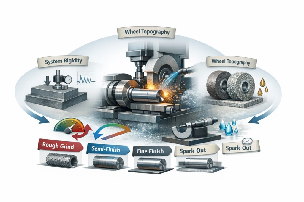
To master high-precision grinding, an engineer must stabilize four critical pillars that define the process limits:
- • System Rigidity: Managing the Force-to-Stiffness Ratio to prevent elastic deflections from translating into geometric errors.
- • Tool Topography: Ensuring the wheel surface is dressed to a specific active grain density (C) for the desired finish.
- • Kinematic Synchronization: Balancing wheel and work speeds to optimize the chip thickness (hcu).
- • Thermal Equilibrium: Controlling the heat flux to avoid dimensional drift caused by thermal expansion.
From Roughing to Finishing: The Precision Workflow
A high-precision grinding cycle is rarely a single-pass operation. It is a multi-stage workflow designed to progressively eliminate the errors introduced in the previous step. The transition from Rough Grinding (focused on Material Removal Rate) to Fine Finishing (focused on Surface Integrity) requires a fundamental shift in parameter logic—moving from maximum power to maximum stability.
This guide provides a structured roadmap for engineers to navigate these choices. We begin with the most critical preliminary decision: matching the abrasive tool to the material to ensure the process starts from a stable foundation. In the next section, we look at Workpiece Material & Wheel Matching.
2. Preliminary Step: Workpiece Material & Wheel Matching
Before a single parameter is entered into the machine controller, the Abrasive-Workpiece Affinity must be established. High-precision grinding fails when the wheel is either too hard (causing burn) or too soft (causing rapid loss of form). The choice of abrasive grain—Alumina, Silicon Carbide, CBN, or Diamond—is governed by the chemical and mechanical properties of the workpiece material.
Hardness vs. Thermal Conductivity
For precision components, we must consider how the material dissipates heat. Materials with low thermal conductivity, such as certain superalloys or ceramics, require “cool-cutting” wheels with Induced Porosity to carry more coolant into the cut. Harder materials require abrasives with high Friability, where the grains break predictably to maintain sharpness, preventing the force spikes that lead to geometric inaccuracies.
The Bond System Selection
The bond holds the grains in place and determines the wheel’s Elastic Modulus. For ultra-precision finishing, Vitrified Bonds are preferred due to their high rigidity and ability to be dressed with extreme precision. For applications requiring superior surface finishes (nanometer-scale Ra), Resin Bonds provide a degree of “cushioning” that minimizes micro-scratching.
Once the tool and material are harmonized, the engineer must establish the kinematic speeds that will drive the material removal process. This sets the baseline for the entire grinding cycle. In the next section, we look at Step 1: Establishing the Kinematic Baseline.
3. Step 1: Establishing the Kinematic Baseline (vs & vw)
The foundation of any grinding cycle is the Speed Ratio (q), which is the relationship between the wheel peripheral speed (vs) and the workpiece speed (vw). For high-precision components, these velocities are not just about throughput; they determine the thickness of the chips being removed and, consequently, the magnitude of the forces acting on the part.
Wheel Speed (vs) and Surface Integrity
In precision grinding, we typically aim for higher wheel speeds (within the safety limits of the bond) to achieve Kinematic Thinning. By increasing vs, the undeformed chip thickness decreases, which directly reduces the roughness (Ra) and the normal force that causes deflection. For ultra-precision components, a stable vs with minimal spindle runout is mandatory.
Speed Ratio (q) Management
The ratio q = vs / vw is a critical diagnostic tool. For most precision steel grinding, a q-ratio between 60:1 and 120:1 is standard. A ratio that is too high (low vw) can lead to localized heat buildup and “glazing” of the wheel, while a ratio that is too low (high vw) increases the chip thickness, leading to “chatter” and poor surface finish.
Setting the kinematic baseline ensures that the machine and wheel are working in their most efficient speed range. However, the actual removal of material happens through the depth of cut. In the next section, we look at Step 2: Depth of Cut (ae) and Incremental Feed Strategy.
4. Step 2: Depth of Cut (ae) and Incremental Feed Strategy
In high-precision grinding, the total stock removal is never achieved in a single pass. Instead, it is partitioned into a Decremental Feed Strategy. This approach minimizes the accumulation of grinding forces and thermal energy, ensuring that the machine’s Elastic Deflection is progressively reduced as the component reaches its final dimension.
Partitioning the Removal Process
A deterministic cycle is typically divided into three distinct phases: Roughing, Semi-finishing, and Finishing. Each phase has a specific purpose—Roughing removes bulk material, Semi-finishing establishes the geometric form, and Finishing achieves the final surface texture and residual stress state.
The Rule of Diminishing Feed
To maintain sub-micron control, the Radial Infeed (ae) must be reduced as the part approaches size. If the finishing infeed is too large, the resulting normal force will cause the machine to “spring back,” leaving the part oversized. Conversely, an infeed that is too small can lead to Rubbing, which generates heat without removing material.
A practical habit that helps in production is to treat each phase as a “measurement checkpoint.” After semi-finishing, we often pause just long enough to confirm roundness trend and thermal drift direction (not only the absolute size). If the drift direction flips between parts, it’s usually a thermal or coolant consistency issue—not a need for more infeed. This small checkpoint prevents chasing microns with parameter changes that create new variables.
Managing Machine “Constant” (Deflection)
Every machine has a specific Stiffness (k). The actual depth of cut is always slightly less than the programmed infeed due to system deflection (x = Fn / k). By using a decremental feed, we ensure that the force Fn is at its lowest during the final pass, allowing the machine to return to its “zero-deflection” state.
Even after the final infeed pass, residual forces remain in the system. To eliminate these and achieve the ultimate geometric truth, we must utilize the “Spark-out” phase. In the next section, we look at Step 3: Spark-out Cycles and Geometric Correction.
5. Step 3: Spark-out Cycles and Geometric Correction
In the hierarchy of high-precision parameters, Spark-out is the most critical phase for achieving geometric perfection. Spark-out is the process of allowing the grinding wheel to pass over the workpiece several times without any additional radial infeed. This allows the accumulated Elastic Deflection in the machine spindle, wheel, and workpiece to “relax” or dissipate as the residual forces drop to zero.
The Force Decay Phenomenon
During the active infeed stages, the machine system acts like a compressed spring. When the infeed stops, the “stored” force continues to drive the wheel into the material at an exponentially decreasing rate. Without sufficient spark-out time, the part will consistently remain oversized, or worse, exhibit Form Errors like lobing or taper due to uneven force release.
Quantifying the Number of Passes
The required number of spark-out passes is governed by the System Time Constant (τ), which depends on the material’s specific energy and the machine’s static stiffness. For standard precision, 2 to 4 passes may suffice. However, for ultra-precision components with sub-micron roundness requirements, 6 to 10 passes are often necessary to ensure the normal force (Fn) has completely decayed.
Dangers of Excessive Spark-out
While spark-out is beneficial, it is not without risk. If the cycle is too long, the wheel can begin to Glaze or develop wear flats because there is no fresh material to trigger self-sharpening. This can paradoxically increase the temperature in the contact zone, leading to thermal damage. Therefore, the spark-out must be precisely timed to end exactly when the forces have reached equilibrium.
With the kinematics and cycle timing optimized, the final determining factor for the surface finish is the wheel’s micro-geometry. In the next section, we look at Step 4: Dressing Strategy for Finishing Topography.
6. Step 4: Dressing Strategy for Finishing Topography
The surface roughness (Ra) of a high-precision component is a direct replica of the Wheel Topography. In the finishing stage, the goal of dressing shifts from maximizing material removal to creating a “closed” and stable wheel surface. This is achieved by manipulating the Dressing Overlap Ratio (Ud) to control the density and height of the active cutting edges.
The Overlap Ratio (Ud) for Finishing
For high-precision finishing, we utilize a high overlap ratio, typically between 6 and 10. This means the dresser passes over each point on the wheel multiple times, “crushing” the abrasive grains to a uniform height and creating more Active Cutting Points (C). A higher density of smaller cutting points results in smaller individual chips and a significantly lower surface roughness.
Dressing Lead and Tool Shape
The Dressing Lead (fd) must be precisely controlled. In ultra-precision applications, using a Form Dressing Roll or a CVD Diamond Blade allows for the generation of a perfectly straight wheel face. Any error in the dressing tool’s path will be directly mapped onto the workpiece as a form error (taper or waviness).
Dressing Depth and Thermal Integrity
A common mistake is “over-dressing,” which removes too much material from the wheel and creates a surface that is too smooth, leading to Glazing. In precision finishing, the dressing depth should be just enough to remove the wear flats—typically 2 to 5 μm per pass. This maintains a sharp but fine topography that manages both roughness and the heat flux.
With the wheel surface optimized, the final layer of precision comes from managing the environment. Even the best parameters will fail if the part expands due to heat. In the next section, we look at Step 5: Thermal Management & Coolant Jet Aiming.
7. Step 5: Thermal Management & Coolant Jet Aiming
In ultra-precision grinding, the machine’s greatest enemy is Thermal Expansion. A temperature rise of just 1°C can cause a steel workpiece to expand by several microns, instantly exceeding sub-micron tolerances. For high-precision components, parameter selection must be supported by a Thermal Stabilization Strategy that ensures the heat generated in the grinding zone is immediately evacuated.
Jet Velocity Matching for Precision
As discussed in previous deep-dives, the coolant jet must penetrate the Air Boundary Layer to reach the contact zone. For precision work, the Jet Velocity (vj) should match the wheel speed (vs) at a 1:1 ratio. If the jet is too slow, the air barrier will deflect the fluid, leading to “dry” grinding patches that cause localized thermal growth and “out-of-roundness.”
One of the most revealing checks is surprisingly simple: if burn or size drift appears “randomly,” we first inspect the nozzle and filter before blaming the wheel or the operator. A partially clogged nozzle can look fine to the eye but creates intermittent dry patches at the nip. When the jet is restored, spindle power often drops immediately and the part size stabilizes within a few cycles—an outcome that’s hard to achieve by tweaking speeds alone.
Flow Rate and Dimensional Drift
The volume of coolant is as critical as its placement. A high-precision process requires a constant flow rate that is synchronized with the Specific Grinding Power (Pc). If the coolant flow fluctuates, the bulk temperature of the workpiece will vary, causing the part size to “drift” throughout the production batch. Utilizing a High-Precision Chiller with ±0.1°C control is the industrial gold standard for maintaining the thermal equilibrium of the system.
Once thermal stability is achieved, the process enters a state of Deterministic Control. However, even with a perfect setup, anomalies can occur. In the final section, we provide a Troubleshooting Checklist to quickly diagnose and correct common precision defects.
8. Troubleshooting: Common Precision Defect Solutions
Even with a scientifically grounded setup, the transition from theoretical parameters to a production environment can reveal unexpected defects. For high-precision components, these anomalies are often the result of a mismatch between the Abrasive Topography and the Machine Dynamics. This troubleshooting guide provides a deterministic approach to diagnosing and correcting the most common precision failures.
Diagnostic Hierarchy
When a defect occurs, the corrective action should follow a specific order: first, verify Geometric Stability (dressing and clamping), then Kinematic Matching (speeds and feeds), and finally Thermal Control (coolant delivery). Changing multiple variables at once makes it impossible to identify the root cause.
Conclusion: The Path to Deterministic Precision
High-precision grinding is the ultimate test of an engineer’s understanding of Force, Heat, and Time. By following this structured selection guide—from abrasive matching to thermal stabilization—manufacturers can transition from trial-and-error setups to a state of deterministic excellence. Success in the sub-micron realm is not about luck; it is about the rigorous application of grinding physics to every parameter in the cycle.
Final Practical Rule
“In precision, stability precedes speed. Always establish a rigid, thermally neutral baseline before attempting to maximize material removal.”
References & Further Reading
Technical Publications & Industrial Standards
- • Rowe, W. B. (2014). Principles of Modern Grinding Technology. Academic Press. (Focus: Scientific selection of grinding parameters and thermal damage prevention).
- • Marinescu, I. D., et al. (2007). Handbook of Machining with Grinding Wheels. CRC Press. (Focus: Practical tables for speed, feed, and depth of cut for various materials).
- • Malkin, S., & Guo, C. (2008). Grinding Technology: Theory and Applications of Machining with Abrasives. Industrial Press. (Focus: Analysis of grinding forces and surface finish modeling).
- • Klocke, F. (2009). Manufacturing Processes 2: Grinding, Honing, Lapping. Springer. (Focus: High-precision abrasive processes and system rigidity).
Curated Internal Resources: High-Precision Mastery Series
To implement a deterministic precision cycle and resolve complex geometric errors, explore our core engineering resources:
PARAMETER LOGIC:
Surface Grinding Process Optimization: Strategies for Variable Control and Productivity Enhancement
TOPOGRAPHY CONTROL:
Dressing and Truing Mechanisms: Principles of Wheel Regeneration and Surface Generation
FORCE DYNAMICS:
Mechanics of Grinding Forces: Understanding Tangential/Normal Forces and Force Ratio
Industrial Research & System Providers
- Fraunhofer IPT: Applied research on ultra-precision machining and deterministic manufacturing processes.
- The Grinding Institute: A leading consultancy for grinding cycle optimization and high-precision troubleshooting.
© 2026 Advanced Machining Intelligence | Strategic Resource for Precision Engineering and Deterministic Process Design