1. Introduction: The High-Stakes World of Aerospace Grinding
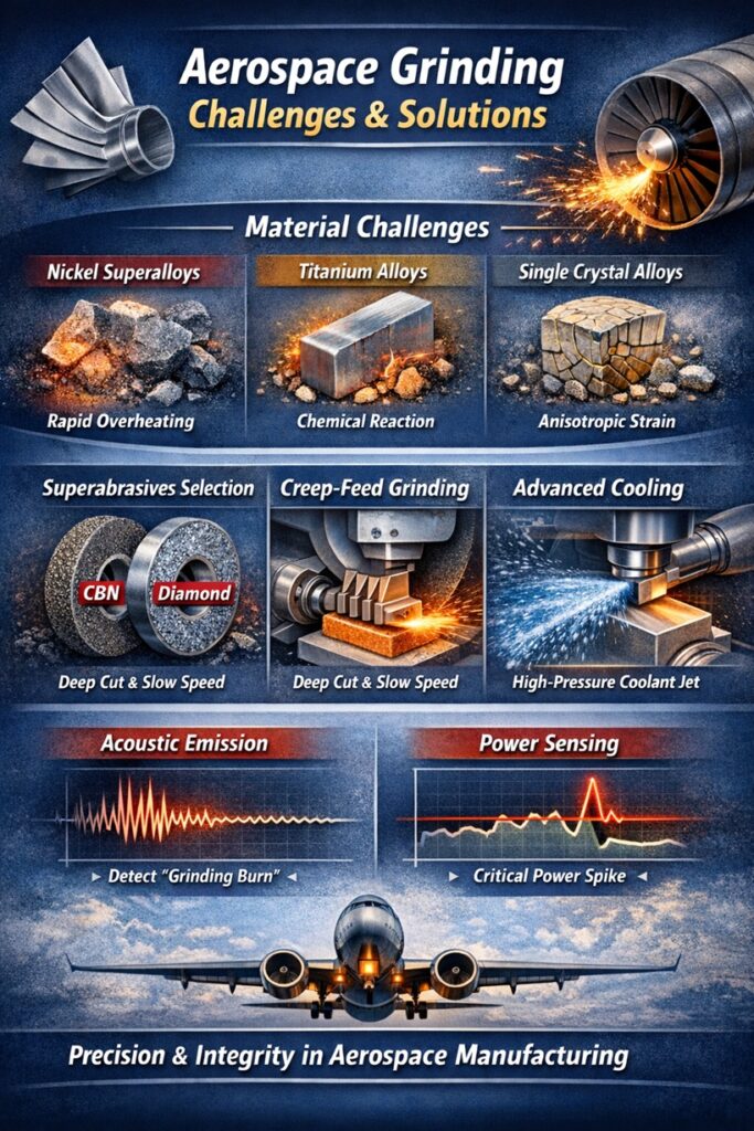
In the aerospace industry, the grinding process is far more than a simple finishing operation; it is a critical manufacturing step for high-value components such as turbine blades, engine disks, and landing gear assemblies. These parts are typically fabricated from Nickel-based Superalloys (e.g., Inconel 718) or Titanium alloys (e.g., Ti-6Al-4V), designed to withstand extreme temperatures and mechanical stresses. Consequently, the grinding of these materials is governed by a “zero-tolerance” policy regarding surface and subsurface defects.
The Complexity of Difficult-to-Cut Materials
Aerospace alloys are engineered for high strength and heat resistance, which paradoxically makes them notoriously difficult to machine. Their Low Thermal Conductivity (λ) and high chemical reactivity mean that the heat generated during grinding does not dissipate into the workpiece or the chips. Instead, it remains concentrated in the Grinding Zone, leading to rapid temperature spikes that can compromise the structural integrity of the component.
The Integrity Bottleneck: Beyond Dimensional Accuracy
Unlike general industrial grinding, where dimensional tolerance is the primary goal, aerospace grinding prioritizes Surface Integrity. Even a minor thermal anomaly can induce Tensile Residual Stresses, localized micro-cracks, or “White Layer” formation (re-hardened martensite). In an environment where a turbine blade rotates at over 15,000 RPM under centrifugal loads, these subsurface flaws act as initiation points for Fatigue Failure, which can be catastrophic.
- • Metallurgical Damage: Overheating causes phase transformations that soften the material.
- • Chemical Alteration: High temperatures trigger reactions between the abrasive and the alloy (e.g., Titanium’s affinity for Carbon).
- • Stress Imbalance: Thermal expansion during cutting leads to permanent tensile stress upon cooling.
To conquer these challenges, engineers must move away from conventional grinding logic and adopt strategies that prioritize thermal management above all else. In the next section, we will analyze the specific physics behind the Thermal Sensitivity of Superalloys & Titanium to understand the mechanics of “Grinding Burn.”
In practice, many of the most serious aerospace grinding failures are not caused by a single obvious mistake, but by small thermal decisions that seemed reasonable at the time. This article is structured around those real-world decision points engineers face on the shop floor.
2. Thermal Sensitivity of Superalloys & Titanium
In aerospace grinding, the thermal partitioning of energy is the deciding factor between a certified part and scrap. Nickel-based superalloys and Titanium alloys possess a High Specific Energy (u) of grinding, meaning they require significant force to remove material. Due to their Low Thermal Conductivity (λ), a disproportionate amount of this energy (often over 70%) is conducted directly into the workpiece surface, causing rapid localized heating.
The Mechanics of Grinding Burn
“Grinding Burn” is not merely a surface discoloration; it is a profound metallurgical change. When the temperature in the contact zone exceeds the Phase Transformation Temperature, the material’s microstructure is altered. In Nickel alloys, this can lead to over-aging of the γ′ (gamma prime) strengthening phase, resulting in a localized loss of hardness and creep resistance.
The “White Layer” Phenomenon
In severe thermal cases, the surface undergoes rapid quenching from the coolant, forming a White Layer. This layer is characterized by extremely high hardness but extreme brittleness. In aerospace components subjected to cyclic loading, the White Layer is a prime site for Stress Corrosion Cracking (SCC) and fatigue crack initiation. Detecting these layers often requires destructive nital etching or Eddy Current testing, as they may exist beneath a visually “perfect” surface.
Titanium and Oxygen Affinity
Titanium alloys present a unique secondary thermal challenge. At elevated grinding temperatures, Titanium becomes highly reactive with Oxygen and Nitrogen in the atmosphere, forming a brittle Alpha-Case layer. This layer drastically reduces the ductility of the surface. Furthermore, Titanium’s chemical affinity for Carbon means that traditional Diamond wheels can suffer from Chemical Wear, requiring specialized abrasive strategies.
To mitigate these intense thermal risks, the first line of defense is the selection of the correct abrasive medium. In the next section, we look at Solution 1: Superabrasive Selection (Vitrified CBN vs. Diamond).
3. Solution 1: Superabrasive Selection (Vitrified CBN vs. Diamond)
For aerospace alloys, conventional abrasives like Aluminum Oxide often fail due to rapid dulling, which exponentially increases the heat flux. The transition to Superabrasives is not a luxury but a technical necessity to maintain a “sharp” cutting action. However, the choice between Cubic Boron Nitride (CBN) and Diamond is governed by the chemical compatibility between the abrasive and the alloy’s alloying elements.
Vitrified CBN for Nickel-Based Superalloys
CBN is the primary solution for Inconel and other Nickel-based superalloys. Unlike Diamond, CBN does not contain Carbon, preventing the Chemical Diffusion that occurs at high temperatures when Carbon atoms migrate into the Nickel matrix. Vitrified-bonded CBN wheels are particularly effective because they allow for controlled Induced Porosity, which aids in carrying coolant directly into the arc of contact—a vital feature for preventing grinding burn.
Diamond Strategy for Titanium Alloys
Titanium alloys (Ti-6Al-4V) are highly abrasive and chemically reactive. While CBN can be used, specialized Diamond Grinding is often preferred for certain Titanium grades to achieve superior surface finishes. However, because Titanium has a strong affinity for Carbon, the grinding must be performed at lower peripheral speeds (vs) or with specialized coatings to prevent the Diamond from “graphitizing” and wearing prematurely.
Wheel Sharpness and Power Density
In aerospace applications, a “dull” wheel is a liability. Superabrasives maintain their Cutting Edge Sharpness significantly longer than conventional grains. This keeps the Specific Grinding Power (P’c) low and predictable, ensuring that the thermal energy remains below the threshold for metallurgical damage throughout the entire production batch.
While the abrasive choice reduces the heat generation, the grinding method determines how that heat is distributed. In the next section, we look at Solution 2: Creep-Feed Grinding (CFG) Strategies, the industry standard for aerospace profile machining.
4. Solution 2: Creep-Feed Grinding (CFG) Strategies
For complex aerospace profiles, such as the “fir-tree” root of a turbine blade, Creep-Feed Grinding (CFG) is the industry standard. Unlike conventional reciprocating grinding, CFG utilizes a very large Depth of Cut (ae)—often the full profile depth in a single pass—combined with a very low Workpiece Speed (vw). This kinematic setup is specifically designed to manage the extreme thermal loads of aerospace alloys.
Thermal Management through Large Arc of Contact
The primary advantage of CFG is the extended Arc of Contact (lc). By spreading the total grinding energy over a larger area, the Specific Heat Flux (qw) entering the workpiece is reduced. However, this large contact area requires massive amounts of coolant to prevent fluid “boiling” within the nip. This is where the synergy between high-porosity vitrified CBN wheels and high-pressure delivery becomes mandatory.
Continuous Dressing (CD) Grinding
To maintain the sharpness required for aerospace superalloys, many CFG operations employ Continuous Dressing (CD). In this mode, a diamond dressing roll remains in contact with the wheel throughout the entire grinding pass. This ensures the wheel topography is constantly regenerated, preventing the buildup of wear flats that lead to thermal spikes and “burn.”
Geometric Stability and Spindle Power
Because CFG involves such a deep cut, the Normal Forces (Fn) are significantly higher than in reciprocating grinding. This requires a machine tool with exceptional static and dynamic stiffness. Any deflection in the machine spindle will result in profile errors on the aerospace part, making Spindle Load Monitoring a vital part of the process control loop.
Regardless of the kinematics, the heat generated must be evacuated effectively. In the next section, we look at the fluid dynamics of the process in Solution 3: Advanced Cooling & Lubrication (Coherent Jet).
Engineers who transition to creep-feed grinding often report that the process feels counterintuitive at first. Taking a much deeper cut at a slower speed appears risky, yet it is precisely this approach that stabilizes heat flow and improves repeatability once the process window is understood.
5. Solution 3: Advanced Cooling & Lubrication (Coherent Jet)
In the aerospace sector, coolant is not merely a “liquid”; it is a Precision Tool. Traditional flood cooling is insufficient for Inconel and Titanium because the high rotational speed of the wheel creates an Air Boundary Layer that acts as a physical barrier. To achieve a “Burn-free” process, the fluid must be delivered as a Coherent Jet—a laser-like stream of fluid that maintains its velocity and shape until it penetrates the contact zone.
The Physics of Jet Velocity Matching
For effective cooling in high-speed aerospace grinding, the nozzle exit velocity (vj) must be matched to the wheel peripheral speed (vs). If vj < vs, the air barrier will deflect the coolant, leading to Film Boiling and immediate surface burn. A coherent jet ensures that the maximum volume of fluid reaches the “nip,” providing both lubrication to reduce Ft and thermal evacuation to stabilize the surface.
Oil vs. Water-Based Fluids for Aerospace
The choice of fluid chemistry is a strategic decision. Neat Oils are often preferred for heavy-duty Creep-Feed Grinding of Nickel alloys because of their superior lubricity, which lowers the heat generation at the source. However, Water-miscible fluids (soluble oils) offer higher convective cooling capacity. For Titanium alloys, specific additives are required to prevent chemical adhesion between the Titanium chips and the wheel topography.
Cleaning Nozzles (Scrubbers)
Aerospace alloys are prone to Wheel Loading (metal chips adhering to the wheel). High-pressure Cleaning Nozzles positioned opposite to the grinding zone are utilized to “scrub” the wheel clean before it re-enters the cut. This maintains the “openness” of the wheel topography, allowing for consistent MRR and preventing localized heat buildup.
Even with optimal cooling, the risk of thermal damage remains. To ensure 100% part integrity, we must look at how to monitor the process in real-time. In the next section, we explore Process Monitoring: Acoustic Emission & Power Sensing.
6. Process Monitoring: Acoustic Emission & Power Sensing
In aerospace manufacturing, the high cost of raw materials and the catastrophic risk of part failure make In-Process Monitoring an absolute requirement. Because thermal damage (grinding burn) often occurs beneath the surface and is invisible to the naked eye, engineers rely on high-frequency sensory data to detect anomalies the moment they occur. This transforms grinding from a “probabilistic” process into a Deterministic Quality Assurance system.
Acoustic Emission (AE) for Subsurface Integrity
Acoustic Emission (AE) sensors detect high-frequency elastic waves generated by the interaction between the abrasive grains and the workpiece. Unlike traditional power monitoring, AE is sensitive enough to detect the “friction” of a dull wheel before it generates enough heat to burn the part. In aerospace alloys, a specific “AE signature” corresponds to efficient cutting; any shift toward lower frequencies or increased amplitude signals Wheel Glazing or the onset of Phase Transformation.
Power Spikes and Thermal Correlation
The Spindle Power (Ps) is a direct proxy for the energy entering the grinding zone. By setting strict “Upper Control Limits” (UCL) on the power curve, the machine can automatically abort a cycle if the energy exceeds the calculated Critical Heat Flux. This is vital during the grinding of turbine blades, where even a slight variation in casting thickness can lead to unexpected power spikes and localized overheating.
Digital Twin and Process Logging
For aerospace compliance (NADCAP/FAA), every part must have a Digital Process Trace. Modern monitoring systems log all sensory data for every single part. If a component is later found to have a fatigue issue, engineers can “rewind” the data to see if there was a subtle power fluctuation during its manufacture, allowing for precise root-cause analysis and batch containment.
Monitoring ensures the part is “safe” during the cut, but the ultimate performance of the component is determined by its final stress state. In the next section, we look at Post-Process Integrity: Residual Stress Management.
7. Post-Process Integrity: Residual Stress Management
For aerospace components, the final quality of a part is not measured solely by its surface roughness or dimensional precision. The most critical “invisible” metric is the state of Residual Stress. Residual stress is the internal stress remaining in the material after all external loads and heat sources have been removed. In high-cycle fatigue environments like jet engines, the distribution of these stresses determines whether a part will last 5,000 hours or fail at 500.
Tensile vs. Compressive Residual Stress
Grinding inherently creates two competing types of stress. Thermal expansion during the cut causes the surface to want to “grow,” but it is constrained by the cold material beneath. Upon cooling, this layer shrinks and enters a state of Tensile Residual Stress, which pulls the material apart and promotes crack propagation. Conversely, the Mechanical Action of the abrasive grains “peens” the surface, creating Compressive Residual Stress, which pushes the material together and significantly inhibits crack growth.
Engineering the “Compressive Layer”
The goal of aerospace grinding is to maximize the depth and magnitude of the compressive layer. This is achieved by shifting the process from “thermal-dominant” to “mechanical-dominant.” Using sharp superabrasives, lower wheel speeds (vs), and optimized spark-out cycles ensures that the mechanical deformation of the grains outweighs the thermal expansion, leaving the part in a robust, fatigue-resistant state.
Verification via X-Ray Diffraction (XRD)
In the aerospace industry, critical components often undergo X-Ray Diffraction (XRD) testing to map the residual stress profile. This non-destructive method measures the “lattice strain” within the crystal structure of the alloy. If a batch of parts shows a shift toward tensile stress, it serves as an immediate indicator that the grinding process has drifted—potentially due to wheel wear or coolant degradation—requiring immediate intervention.
As we master these current challenges, the industry continues to evolve toward even more complex materials and hybrid methods. In our final section, we conclude with The Future of Aerospace Abrasive Machining.
8. Conclusion: The Future of Aerospace Abrasive Machining
As aerospace engineering pushes toward higher engine efficiencies and lighter airframes, the demand for even more extreme materials—such as Ceramic Matrix Composites (CMCs) and Gamma Titanium Aluminides—continues to grow. These materials present a new frontier for grinding technology. The future of aerospace abrasive machining lies in the integration of Digital Twins, real-time Artificial Intelligence, and hybrid processes that redefine the boundaries of what is possible.
Hybrid Processes: Laser-Assisted Grinding
One of the most promising emerging technologies is Laser-Assisted Grinding (LAG). By using a high-power laser to localizedly soften the material just millimeters ahead of the grinding wheel, the grinding forces can be reduced by up to 50%. This allows for the machining of extremely brittle ceramics or ultra-hard superalloys at much higher removal rates, effectively bypassing the traditional “stiffness-limited” barriers of conventional machines.
Smart Wheels and the “Connected” Factory
The next generation of grinding wheels will be “smart,” featuring embedded wireless sensors that transmit temperature and force data directly from the Grinding Zone to the machine’s control unit. This real-time feedback allows for Autonomous Process Correction, where the machine can adjust its own vs and vw on the fly to stay within the optimal “Burn-free” window, eliminating the need for post-process destructive testing.
The Aerospace Grinding Manifesto
“In the aerospace domain, the wheel does not just shape the part; it forges its destiny. Mastery of the thermal-mechanical interaction is the only path to safety, reliability, and flight-ready excellence.”
This concludes our 10-part series on Deterministic Grinding Intelligence. From the foundational mechanics of forces to the extreme challenges of aerospace alloys, the goal has remained the same: to transition from trial-and-error to a state of scientific excellence. By applying these principles, manufacturers can ensure that every micron removed is a step toward perfect engineering.
References & Further Reading
Technical Publications & Industrial Standards
- • Malkin, S., & Guo, C. (2008). Grinding Technology: Theory and Applications of Machining with Abrasives. (Focus: Thermal analysis of nickel-based superalloys and heat partitioning).
- • E. Brinksmeier, et al. (2006). Surface Integrity of Machined Components. CIRP Annals. (Focus: Residual stress management and metallurgical damage in aerospace alloys).
- • K. Tönshoff (2002). Abrasive Machining of Advanced Aerospace Materials. (Focus: Creep-feed grinding mechanics and CBN wheel application for Inconel).
- • AMS 2430 Standard. Shot Peening & Surface Integrity Requirements. (Focus: Comparison of industrial standards for compressive residual stress verification).
Curated Internal Resources: Aerospace Integrity Series
To ensure the mechanical reliability and fatigue life of aerospace components, we recommend exploring the following foundational modules:
Aerospace Material Research Institutions
- The Advanced Manufacturing Research Centre (AMRC): Global leader in aerospace machining innovation and high-performance alloy optimization.
- NIST Manufacturing Engineering: Dedicated to setting standards for subsurface integrity and residual stress measurement in mission-critical parts.