Disclaimer
This report is intended for technical reference and educational purposes only. The engineering principles, formulas, and qualitative analyses provided are based on established tribological and metallurgical theories. All performance outcomes and thermal behaviors are subject to specific operational variables including, but not limited to, material properties, machine stiffness, and environmental conditions. No specific quantitative improvements are guaranteed without site-specific empirical validation.
1. Introduction: The Strategic Impact of Grinding Burn
In precision manufacturing, surface integrity is the primary benchmark for component reliability. Among the various forms of surface degradation, Grinding Burn represents a critical failure mode where excessive thermal energy induces irreversible metallurgical changes in the workpiece. This phenomenon is not merely a cosmetic defect characterized by oxidation colors; it is a fundamental shift in the material’s structural properties that can lead to catastrophic field failures.
The Invisible Threat: Oxidation vs. Metallurgical Damage
The severity of grinding burn is often underestimated because its most visible sign—surface discoloration—can be removed by subsequent finishing. However, the underlying thermal damage remains. We must distinguish between superficial chemical changes and deep structural degradation:
The Energy Threshold and Surface Integrity
The onset of grinding burn is governed by the Critical Heat Flux (qc). When the heat generated in the grinding zone exceeds the collective heat-sink capacity of the system, the surface temperature reaches the transition point (Tcrit). This thermal energy balance is the fundamental condition for process stability:
Thermal Integrity Balance Condition
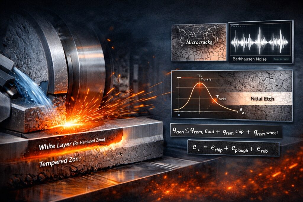
qgen ≤ qrem, fluid + qrem, chip + qrem, wheel
Failure to maintain this thermal equilibrium results in localized damage tiers that severely degrade the component’s performance:
- Level 1: Tempering Softening – Thermal exposure reduces the martensitic hardness, compromising the sub-surface wear resistance and load-bearing capacity.
- Level 2: Tensile Residual Stress – Differential thermal expansion and contraction cycles create internal pulling forces, serving as precursors to fatigue failure.
- Level 3: Re-hardening (White Layer) – Extreme heat followed by rapid quenching forms a brittle, “white-etching” layer, significantly increasing the risk of micro-cracks.
By systematically analyzing the root causes of thermal distress, manufacturers can transition from reactive defect management to a deterministic prevention strategy. The subsequent chapters will detail the physics of energy partition and fluid dynamic barriers that define the boundaries of grinding integrity.
2. Thermal Equilibrium in the Grinding Zone
The occurrence of grinding burn is fundamentally a result of energy partition failure. Unlike conventional cutting processes where the majority of heat is carried away by the chips, grinding is a high-specific-energy process where a significant portion of the total energy is dissipated into the workpiece as heat.
The Concept of Specific Grinding Energy (ec)
To analyze the thermal load, we must first define the Specific Grinding Energy (ec), which represents the energy required to remove a unit volume of material. This total energy is the sum of several distinct physical interactions at the interface:
Specific Grinding Energy Decomposition
ec = echip + eplough + erub
Energy Partitioning and the Partition Ratio (Rw)
The Partition Ratio (Rw) is the fraction of the total grinding energy that enters the workpiece. Minimizing this ratio is the primary objective for preventing thermal damage. The distribution of energy can be summarized by the following heat sinks:
- Workpiece Conduction (Rw): Energy absorbed by the material, directly causing temperature elevation and potential phase transformation.
- Chip Convection: Energy removed by the ejected micro-chips. In grinding, this is limited by the small size of the chips and the high energy required for their formation.
- Fluid Convection (hf): The heat flux removed by the metalworking fluid. This is highly dependent on the fluid’s ability to penetrate the grinding zone.
- Wheel Conduction: A minor portion of heat conducted into the abrasive grains and bond material.
Critical Temperature Thresholds
Thermal damage occurs when the surface temperature (Ts) exceeds the material-specific critical threshold. The relationship between heat flux and temperature rise is governed by the thermal properties of the workpiece:
Understanding these energy distribution mechanisms is the first step in deterministic process control. By managing the Specific Grinding Energy and the Partition Ratio, manufacturers can prevent the accumulation of heat that leads to metallurgical failure.
3. The Mechanics of Friction: Rubbing, Ploughing, and Cutting
The generation of heat in grinding is primarily determined by the interaction stages between the abrasive grit and the workpiece surface. Unlike ideal cutting, where energy is used to create chips, a significant portion of grinding energy is “wasted” through friction and plastic deformation, which are the primary drivers of grinding burn.
The Three Stages of Grit-Workpiece Interaction
As an individual abrasive grain engages with the material, it passes through three distinct phases. The energy efficiency of the process depends on the transition point between these stages:
- 1. Rubbing Phase: The grain slides over the surface without penetration. Nearly 100% of the energy in this phase is converted into frictional heat, significantly increasing the workpiece temperature without any material removal.
- 2. Ploughing Phase: The grain penetrates the surface but lacks the critical depth to form a chip. Instead, it displaces material laterally and ahead of the grit, resulting in plastic deformation and internal heat generation.
- 3. Cutting Phase: The grain reaches the Critical Undeformed Chip Thickness (hcu, crit). At this stage, material is finally removed as a chip, which carries away a portion of the thermal energy.
The Role of “Wear Flats” in Heat Acceleration
As grinding progresses, abrasive grains lose their sharpness, forming wear flats (attritious wear). These flattened areas increase the contact area between the grain and the workpiece, shifting the energy balance back toward the inefficient Rubbing phase.
Kinematic Analysis of Heat Flux
The heat flux generated during these interactions is a function of the Tangential Grinding Force (Ft) and the Wheel Speed (vs). Any factor that increases the sliding friction directly elevates the total heat input:
Total Heat Flux Generation (qt)
qt = (Ft × vs) / (b × lc)
As the Rubbing and Ploughing phases dominate, the Ft increases disproportionately to the material removal rate, causing the heat flux to surpass the cooling capacity of the environment. This necessitates a fluid that not only cools but lubricates to delay the transition from Cutting to Rubbing.
4. Hydrodynamic Barriers and the Leidenfrost Effect
Providing a sufficient volume of metalworking fluid (MWF) to the machine is not a guarantee of effective cooling. In high-speed grinding, physical barriers often prevent the fluid from entering the contact zone. When these barriers cause a cooling failure, the temperature can rise to a level where the fluid itself becomes an insulator.
The Air Barrier (Boundary Layer) Problem
As the grinding wheel rotates at high peripheral speeds (vs), it carries a high-pressure air boundary layer. This air envelope acts as a shield, deflecting the coolant jet away from the grinding interface. If the jet velocity (vj) does not match or exceed the wheel speed, the fluid cannot penetrate this barrier.
Condition for Jet Penetration
vj ≅ vs
Film Boiling and the Leidenfrost Effect
Even if the fluid penetrates the air barrier, its effectiveness is limited by the Boiling Incipience Temperature. When the heat flux exceeds a certain threshold, the fluid in contact with the workpiece reaches its boiling point and undergoes a phase change into vapor.
This leads to the Leidenfrost Effect, where a continuous vapor film (gas phase) forms between the liquid and the hot surface. Since gases have significantly lower thermal conductivity than liquids, the heat transfer coefficient (h) drops abruptly, causing a catastrophic “thermal spike” in the workpiece.
Implications for Fluid Choice
To mitigate these hydrodynamic and thermodynamic failures, the fluid must possess:
- High Thermal Conductivity: To delay the onset of nucleate and film boiling.
- Low Foaming Tendency: To ensure the jet maintains a coherent, high-density stream capable of breaking the air barrier.
- Optimized Viscosity: To facilitate rapid penetration into the grinding zone at high jet pressures.
By synchronizing fluid delivery (vj) with the kinematics of the wheel (vs), the risk of thermal insulation via film boiling can be significantly reduced, maintaining the integrity of the workpiece surface.
5. Wheel Topography and Loading Phasing
The surface topography of a grinding wheel plays a pivotal role in controlling the thermal energy generated during the process. Specifically, the phenomenon of loading—where swarf (metallic chips) becomes embedded within the wheel pores—acts as a critical barrier to coolant delivery and a primary driver for rapid heat accumulation.
Loss of Chip Evacuation Space and Secondary Rubbing
Wheel pores serve as vital conduits for transporting metalworking fluid into the contact zone and carrying generated chips out of the process. When loading occurs, this space is physically occupied by metallic debris, triggering a cascade of thermal failures:
- Degradation of Effective Porosity: The physical path for coolant penetration is obstructed, leading to a sharp decline in convective cooling efficiency.
- Chip-to-Workpiece Friction: Embedded swarf rubs aggressively against the workpiece surface, generating secondary frictional heat that bypasses the primary cutting action.
- Elevation of Grinding Forces: As the wheel’s cutting ability diminishes, the energy required for material removal increases, raising the spindle load and the rate of heat conversion.
Detergency and Thermal Integrity
Maintaining an “open” wheel topography requires a fluid with high detergency. Fluids with superior cleaning properties work alongside centrifugal forces to continuously eject metallic fines from the wheel surface, preventing them from fusing with the bond material.
Self-sharpening and Critical Temperatures
In ideal grinding, self-sharpening occurs as worn grains fracture or dislodge. However, when heat accumulates due to loading, the abrasive bond may soften or swarf may weld to the grit, inhibiting this process. This creates a vicious cycle that dulls the wheel further and inevitably leads to the onset of grinding burn.
Process Stability Logic
High Detergency → Open Wheel Topography → Optimized Chip Evacuation → Lower Heat Flux (qt)
Consequently, managing wheel topography is not merely a task of tool maintenance; it must be understood as a critical hydrodynamic filtering process that governs the flow of thermal energy into the workpiece.
6. Metallurgical Degradation: Re-hardening and Residual Stress
The most critical consequence of grinding burn is the permanent alteration of the workpiece’s microstructure. When the thermal energy exceeds the material’s phase transformation threshold, it triggers a series of metallurgical events that compromise the mechanical integrity of the component.
Phase Transformation and the Formation of “White Layer”
If the surface temperature reaches the Austenitization temperature (Ac3), the surface layer transforms into austenite. As the wheel moves away and the cold bulk of the material or the fluid provides a rapid quench, this austenite transforms into Untempered Martensite.
- The White Layer: Named for its appearance under nital etching, this layer is extremely hard but exceptionally brittle. Its high internal stress makes it a primary site for crack initiation.
- Tempering Softening Zone: Beneath the white layer, a zone of over-tempered martensite often forms. This area suffers from reduced hardness and yield strength, creating a structural “soft spot” in the component.
Residual Stress: From Compression to Tension
Efficient grinding processes aim to leave the surface in a state of Compressive Residual Stress, which inhibits crack growth. However, the high thermal gradients associated with grinding burn shift this state toward Tensile Residual Stress through two mechanisms:
Surface Integrity and Fatigue Life
The presence of tensile residual stress and brittle white layers dramatically reduces the Endurance Limit (Se) of the part. Under cyclic loading, micro-cracks formed within the white layer propagate rapidly through the tensile stress field, leading to premature fatigue failure.
Fatigue Integrity Relationship
Thermal Damage → Brittle Phase Formation → Tensile Stress Field → Accelerated Fatigue Failure
Ultimately, metallurgical degradation turns a high-precision component into a liability. Preventing these changes requires maintaining the grinding temperature below the material’s tempering or transformation points through deterministic control of the energy partition.
7. Material-Specific Burn Sensitivity
Not all materials respond to grinding energy in the same manner. A material’s susceptibility to thermal damage—its Burn Sensitivity—is a complex function of its thermal diffusivity, chemical affinity for the abrasive, and metallurgical stability. Understanding these properties is essential for tailoring the cooling strategy to the specific alloy being processed.
The Role of Thermal Diffusivity (α)
Thermal diffusivity represents how quickly a material can conduct heat away from the grinding zone relative to its ability to store thermal energy. Materials with low diffusivity, such as Titanium alloys and Nickel-based Superalloys (Inconel), act as thermal insulators.
Thermal Diffusivity Relationship
α = k / (ρ × cp)
When α is low, heat is trapped in a thin surface layer, causing the temperature to spike even under moderate grinding forces. Conversely, materials like aluminum or copper dissipate heat rapidly, reducing the risk of localized phase transformation.
Chemical Affinity and Work-Hardening
Beyond thermal properties, the mechanical behavior of the alloy during the Ploughing phase dictates energy consumption. Alloys with high work-hardening rates require more energy to deform, which directly increases the specific grinding energy (ec).
Abrasive-Workpiece Compatibility
Thermal management is also influenced by the chemical compatibility between the material and the abrasive grit. For instance, using aluminum oxide wheels on titanium leads to rapid chemical loading, where the material welds to the grit, increasing the erub component of the total energy and leading to an inevitable burn.
Selecting a fluid for these “sensitive” materials requires a formulation that offers exceptional boundary lubrication to lower friction in the ploughing stage and a high boiling point to maximize the duration of convective cooling before film boiling occurs.
Quick Checklist (Shop-floor)
To maintain thermal integrity on a daily basis, shop-floor supervisors should audit the following deterministic variables before and during production runs:
1. Kinematic Synchronization
Verify Jet Velocity (vj) vs. Wheel Speed (vs). Ensure the coolant jet possesses enough kinetic energy to breach the air boundary layer effectively.
2. Abrasive Condition
Monitor Dressing Intervals closely. Watch for spikes in spindle power, which indicate the formation of wear flats and the onset of the thermal Rubbing phase.
3. Fluid Stability
Check for Foam or Air Entrainment. Entrained air acts as a thermal insulator, drastically reducing the convection heat transfer coefficient (h).
4. Thermal Inspection
Deploy Burn Detection protocols based on part criticality. Validate surface integrity using either Nital Etching or non-destructive Barkhausen Noise analysis.
Burn Detection Selection Guide
8. Conclusion: From Reactive Mitigation to Deterministic Prevention
The analysis of grinding burn reveals that thermal damage is not an inevitable byproduct of the process, but a consequence of a disrupted energy balance. Transitioning from reactive firefighting—detecting defects after they occur—to deterministic prevention requires a holistic mastery of the variables that govern the grinding zone.
Synthesizing the Thermal Control Chain
Achieving surface integrity depends on maintaining a “Thermal Control Chain” where each physical element supports the other. If any link in this chain fails—whether it be fluid delivery, wheel topography, or lubricity—the system rapidly shifts toward the Critical Heat Flux.
- Friction Management: High-performance lubrication minimizes the erub and eplough components, ensuring that the energy partition ratio (Rw) remains low.
- Hydrodynamic Penetration: Synchronizing jet velocity (vj) with wheel speed (vs) is the only way to bypass the air barrier and deliver the heat transfer agent to the contact interface.
- Surface Topography Integrity: Advanced detergency prevents swarf loading, maintaining the hydraulic paths necessary for chip evacuation and convective cooling.
The Economic Value of Prevention
Preventing grinding burn is a strategic investment in Asset Reliability. While the direct costs of fluid and tooling are easily measured, the indirect costs of thermal failure—scrap rates, unplanned machine downtime, and compromised component fatigue life—are far more damaging to long-term profitability.
In conclusion, the mastery of grinding burn requires a deep respect for the physics of the grinding zone. By deploying advanced fluid technologies and optimizing the kinematic variables of the process, manufacturers can eliminate the “burn threshold” as a constraint, allowing for faster cycle times and superior surface integrity.
Author’s Note from the Shop Floor
Grinding burn rarely announces itself with dramatic sparks or visible smoke. In most production environments, it creeps in quietly. Operators first notice that parts feel slightly warmer in the hand, or that the machine’s spindle load sounds “heavier” even though parameters haven’t changed. Dressing intervals shorten, spark-out times stretch, and someone eventually says, “Something’s not cutting like it did last week.”
By the time discoloration appears, the thermal history has already been written into the steel. Maintenance teams often trace these events back not to a single setting mistake, but to a gradual drift — a partially clogged nozzle, rising foam in the sump, a wheel that stayed in service just a little too long, or fluid concentration that slid out of range over several shifts.
Shops that consistently avoid burn are usually not doing one dramatic thing differently. They are simply keeping many small variables under control at the same time: jet aim, wheel openness, fluid condition, and dressing discipline. When those pieces stay aligned, the process sounds steady, the sparks stay calm, and surface integrity stops being something you “check after” and becomes something you naturally maintain during production.
References & Further Reading
Technical Publications & Industrial Standards
- • Rowe, W. B. (2014). Principles of Modern Grinding Technology. Academic Press. (Focus: Thermal models and energy partition).
- • Malkin, S. & Guo, C. (2008). Grinding Technology: Theory and Applications of Machining with Abrasives. Industrial Press. (Focus: Specific energy and burn thresholds).
- • Badger, J. (2020). The Book of Grinding. Abrasive Engineering.
Curated Internal Resources: Grinding Burn Prevention & Analysis
To effectively mitigate thermal damage, it is essential to master the diagnostic and control variables discussed in our specialized series:
Industrial Research Institutions
- •
CIRP: Research on tool wear, process analytics, and energy partition modeling. - •
Advanced Machining Research Centre (AMRC): Practical studies on surface integrity and grinding burn in aerospace alloys.
© 2026 Advanced Machining Intelligence | Strategic Resource for Deterministic Grinding and Thermal Integrity