1. Introduction: The Evolution of Cutting Physics
In the broad taxonomy of manufacturing, Turning and Grinding are often viewed as distinct operations—the former associated with bulk material removal and the latter with final finishing. However, from an engineering perspective, they exist on the same continuum of Subtractive Manufacturing. Both processes rely on the fundamental physics of localized plastic deformation and shear-induced failure of the workpiece material. The transition from the macro-mechanics of turning to the micro-mechanics of grinding is not merely a change in scale; it is an evolution in how energy is distributed and how cutting edges interact with the molecular structure of the material.
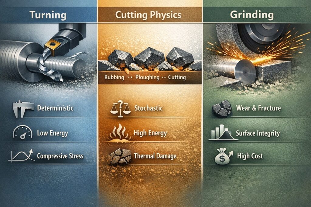
The Common Ancestry: Shear-Based Removal
At the core of both processes lies the Merchant Cutting Model. Whether it is a single carbide insert or a microscopic Al2O3 grain, the tool must apply enough localized pressure to exceed the yield strength of the material, creating a shear plane. In turning, this process is highly Deterministic. The tool geometry—defined by rake and clearance angles—is known, and the path of the chip is predictable. This allows engineers to use linear equations to predict cutting forces and heat generation with high accuracy.
The Grinding Divergence: From Linear to Stochastic
The “Engineering Divergence” occurs when we move from the single-point tool to the Stochastic Multi-Point nature of the grinding wheel. Unlike turning, where every revolution of the spindle engages a known edge, grinding involves thousands of irregularly shaped abrasive grains. These grains possess random orientations, many of which present Negative Rake Angles to the workpiece. This fundamental shift means that the “Cutting” phase is often preceded by “Rubbing” and “Ploughing” phases—physical phenomena that are negligible in turning but dominant in grinding.
This transition forces a re-evaluation of the Size Effect. In turning, as the depth of cut decreases, the specific energy remains relatively stable. In grinding, as the chip thickness (hmax) approaches the radius of the cutting edge, the energy required to remove a unit of material skyrockets. This non-linearity is the defining characteristic of grinding physics, necessitating a move from deterministic models to Statistical Models of material removal.
Objective: Bridging the Theoretical Gap
The purpose of this report is to analyze where the established laws of turning hold firm and where the unique mechanics of grinding take over. By understanding this evolution, engineers can better predict Surface Integrity, optimize Cycle Times, and manage the Thermal Load that defines the success of precision manufacturing. We are not just comparing two machines; we are comparing two different ways of manipulating the physical limits of metal.
The Engineering Thesis: “Grinding is the extreme realization of cutting physics. While turning operates on the macro-geometry of the tool, grinding operates on the micro-geometry of the grain, where the laws of friction often outweigh the laws of shear.”
2. Kinematics: Defined Geometry vs. Stochastic Multi-Point
In turning, the kinematics of material removal are dictated by a rigid, single-point tool with a geometry that is meticulously specified. The engineer can define the Back Rake Angle, Side Rake Angle, and Lead Angle to optimize chip flow and minimize cutting forces. In grinding, however, the “tool” is a collection of thousands of abrasive grains bonded together in a matrix. This transition from a single, defined edge to a Stochastic Multi-Point system fundamentally alters the kinematic relationship between the tool and the workpiece.
The Complexity of Uncut Chip Thickness (hmax)
In turning, the uncut chip thickness is a simple function of the feed rate and the tool’s approach angle. It remains constant throughout a steady-state cut. In grinding, because the grains are distributed randomly and vary in shape, we cannot measure a single “chip thickness.” Instead, we must rely on the Maximum Uncut Chip Thickness (hmax) model, which calculates the theoretical thickness based on wheel speed (vs), work speed (vw), and the active grain density (C).
The engineering challenge here is that hmax in grinding is typically an order of magnitude smaller than in turning—often ranging from 0.1 to 5 microns. At this scale, the Size Effect becomes dominant. Because the cutting edge of a grain is not perfectly sharp (it has a finite tip radius), the extremely small hmax means that the grain often fails to penetrate the surface initially, leading to the “Ploughing” and “Rubbing” phases that are non-existent in macro-turning.
The Negative Rake Angle Penalty
Perhaps the most significant kinematic difference is the Effective Rake Angle. Turning inserts are generally designed with positive or neutral rake angles to reduce cutting forces and facilitate chip shearing. Grinding grains, due to their irregular and crushed shapes, often present Large Negative Rake Angles (typically -30° to -60°).
A negative rake angle converts the cutting process from “shearing” to “plowing.” Instead of the material flowing smoothly over the tool face, it is compressed and pushed aside, generating massive amounts of internal friction and heat. This kinematic “inefficiency” is the reason grinding requires such high specific energy. While a turning tool “slices,” a grinding grain “bruises” its way through the metal before finally initiating a chip.
The Kinematic Axiom: “In turning, the tool dictates the chip. In grinding, the grain negotiates with the material. The unpredictability of the grain’s orientation is what forces grinding to be a statistical process rather than a purely geometric one.”
3. The Three-Stage Mechanism: Beyond Simple Cutting
In conventional turning, the physics of material removal is relatively straightforward: the tool edge penetrates the workpiece, and a chip is formed through continuous shear. This is essentially a single-stage “Cutting” process. Grinding, however, is far more complex. Because of the extremely small uncut chip thickness (hmax) and the bluntness of abrasive grains relative to that thickness, the material removal occurs through three distinct, overlapping stages: Rubbing, Ploughing, and Cutting.
Stage 1: Rubbing (Elastic Deformation)
As an abrasive grain first makes contact with the workpiece, the initial forces are insufficient to penetrate the surface. During this Rubbing phase, the energy is consumed entirely by elastic deformation and friction. No material is removed, but significant heat is generated at the interface. In turning, this phase is negligible due to the sharp edge and large depth of cut, but in grinding, rubbing can account for a substantial percentage of the total energy consumption, especially when the wheel is “glazed” or dull.
Stage 2: Ploughing (Plastic Flow)
As the grain penetrates deeper, the force exceeds the yield strength of the material, but it still hasn’t reached the threshold for shear failure (chip formation). During this Ploughing phase, the material is pushed aside and ahead of the grain, forming “ridges” on the sides of the grinding path. This is Plastic Deformation without removal.
Ploughing is a unique hallmark of grinding. It consumes a massive amount of specific energy and is the primary reason for the high temperatures associated with the process. In turning, the tool is designed to minimize this lateral flow, but the negative rake angles of grinding grains make ploughing an inevitable part of the kinematics.
Stage 3: Cutting (Actual Chip Formation)
Only when the grain reaches a Critical Depth of Engagement does actual shearing occur, resulting in the formation of a microscopic chip. This is the only “productive” stage of the three. However, even in this stage, the energy efficiency is lower than in turning because of the size effect and the high friction on the grain’s wear flat.
The Energetic Axiom: “In turning, energy is spent on creation (the chip). In grinding, energy is spent on struggle (overcoming friction and flow). This ‘struggle’ is what necessitates the advanced cooling and rigid machine structures unique to the grinding process.”
4. Energetics: Why Specific Energy (us) Defies Linear Scaling
In any machining process, Specific Energy (us) is defined as the energy required to remove a unit volume of material. In conventional turning, this value is relatively stable for a given material. However, in grinding, us is typically 10 to 100 times higher than in turning. This discrepancy is not merely a matter of scale; it is the result of the Size Effect and the fundamental shift in how heat is partitioned within the cutting zone.
The Size Effect: The Law of Diminishing Returns
The Size Effect dictates that as the chip thickness (hmax) decreases, the energy required to remove material increases. In turning, where chip thickness is large, the material behaves as a continuum. In grinding, the chip thickness is so small that the grains often encounter a “dislocation-free” zone or work-hardened surface layers.
Furthermore, as discussed in Chapter 2, the bluntness of the grain relative to the chip thickness means that the “cutting” component of energy becomes a minority. The vast majority of the specific energy in grinding is consumed by Rubbing and Ploughing. This makes grinding an inherently “energy-inefficient” process compared to turning, but this inefficiency is the price paid for extreme geometric precision.
Heat Partitioning (Rw): Where the Energy Goes
The most critical engineering difference between the two processes is Heat Partitioning. In turning, approximately 80% to 90% of the generated heat is carried away by the chip. Because the chip is large and the contact time with the tool is short, the workpiece remains relatively cool.
In grinding, the situation is reversed. Due to the high friction and the microscopic size of the chips (which have little thermal mass), the chips cannot carry much heat away. Instead, 60% to 80% of the total energy is conducted directly into the Workpiece. This high Heat Partition Ratio (Rw) is what leads to Grinding Burn, phase transformations, and tensile residual stresses—risks that are significantly lower in conventional turning operations.
The Thermodynamic Axiom: “Turning is a shearing process that generates heat as a byproduct. Grinding is a friction process that generates chips as a byproduct. This fundamental reversal of energy flow is what dictates every decision in coolant delivery and process control.”
5. Tool Life Dynamics: Wear vs. Self-Sharpening
In turning, tool life is governed by the deterministic Taylor’s Equation (VTn = C), where tool failure is a predictable function of cutting speed and time. The failure of a carbide insert is usually defined by a specific threshold of Flank Wear (VB) or Crater Wear. In grinding, however, the “tool” is a living, evolving structure. The life of a grinding wheel is not measured in minutes of contact, but through the G-Ratio (the volume of material removed divided by the volume of wheel wear), and its performance is dictated by a cycle of destruction and renewal known as Self-Sharpening.
The Three Modes of Wheel Wear
Unlike the localized wear of a turning insert, a grinding wheel degrades through three distinct microscopic mechanisms. Understanding these is vital for maintaining the Specific Grinding Energy (us):
- Attritious Wear: The dulling of individual grain tips. This is equivalent to flank wear in turning and leads to increased rubbing and heat.
- Grain Fracture: The microscopic breaking of a grain to reveal new, sharp edges. This is a productive wear mode unique to grinding.
- Bond Fracture: The total release of a dull grain from the wheel matrix. This “Shedding” prevents the wheel from glazing.
Self-Sharpening: The Dynamic Equilibrium
The most profound engineering difference is that a grinding wheel can, under the right conditions, sharpen itself. In turning, once an edge is dull, it must be indexed or replaced. In grinding, as Attritious Wear increases, the grinding forces rise. These elevated forces eventually exceed the strength of the grain or the bond, causing Fracture and exposing new, sharp cutting points.
This creates a Dynamic Equilibrium. If the wheel is too “hard” (the bond is too strong), it will not self-sharpen, leading to glazing and burn. If it is too “soft,” it will wear too quickly, losing geometric accuracy. In turning, the tool’s geometry is a constant; in grinding, the geometry is a Statistical Variable that the engineer manages through wheel grade selection and dressing parameters.
The G-Ratio vs. Tool Life Minutes
In turning, “Tool Life” is a binary state: it is either cutting or it is failed. In grinding, we use the G-Ratio to quantify efficiency. A high G-Ratio (e.g., 2000 for CBN) indicates a very stable tool, while a low G-Ratio (e.g., 20 for Al2O3 on hardened steel) indicates a wheel that is rapidly breaking down. Unlike turning, where the tool is a sunk cost, the grinding wheel’s wear rate is a Process Parameter that can be tuned to balance production speed against abrasive cost.
The Dynamic Axiom: “A turning tool dies slowly and predictably. A grinding wheel lives through a cycle of controlled failure. Managing tool life in grinding is not about avoiding wear, but about orchestrating the destruction of dull grains to maintain the integrity of the cut.”
6. Surface Integrity: Mechanical vs. Thermal Domination
The ultimate objective of any finishing process is to achieve a specific Surface Integrity. This includes not just the visual roughness, but the metallurgical state of the subsurface layers. In turning, surface integrity is primarily a result of Mechanical Loading. In grinding, however, the process is dominated by Thermal Loading. This reversal of dominance creates fundamentally different profiles of residual stress and surface topography.
Residual Stress: Compression vs. Tension
Residual stress is the “hidden” stress left in a material after machining. In turning, the sharp tool edge applies high compressive forces that plastically deform the surface. This mechanical action typically induces Compressive Residual Stress, which is highly beneficial for fatigue life.
In grinding, the high specific energy (us) and heat partition (Rw) discussed in Chapter 4 result in localized thermal expansion. As the surface cools and attempts to contract against the cooler substrate, Tensile Residual Stress is formed. If not managed through proper coolant delivery and wheel selection, these tensile stresses can lead to micro-cracking or “Grinding Burn,” significantly reducing the part’s operational life.
Modeling Roughness (Ra): Feed vs. Abrasive Density
In turning, surface roughness is a deterministic geometric result of the tool’s Nose Radius (rε) and the Feed Rate (f). The theoretical roughness is calculated using the formula Ra ≈ f2 / (32rε). This makes surface finish highly predictable.
In grinding, the surface is a Stochastic Map of thousands of grain paths. Roughness is not governed by a single radius but by the Grain Size, Dressing Lead, and the Active Grain Density. Because the grains are microscopic, grinding can achieve finishes (Ra < 0.1 μm) that are physically impossible for conventional turning tools, but the variability is higher due to the probabilistic nature of grain engagement.
Subsurface Alterations: The “White Layer”
Both processes can induce a “White Layer”—a hard, brittle martensitic structure—but through different mechanisms. In turning, it is often a result of extreme Strain Hardening. In grinding, it is almost exclusively a Thermal Re-hardening phenomenon. For aerospace and medical components, detecting and preventing this thermal damage is the primary reason why grinding processes require much more rigorous validation than turning.
The Integrity Axiom: “In turning, the surface is carved by force. In grinding, the surface is tempered by heat. Success in grinding requires an engineer to act more like a metallurgist than a machinist, managing the thermal energy to protect the integrity of the material.”
7. Practical Trade-offs: Hard Turning vs. Grinding
For decades, grinding was the only viable method for machining materials with a hardness exceeding 45 HRC. However, the development of PCBN (Polycrystalline Cubic Boron Nitride) and advanced ceramic inserts has enabled Hard Turning to compete directly with grinding in the finishing of hardened steels. This shift has created a complex decision-making matrix for production engineers. Choosing between the two requires a balance of initial investment, cycle time, and the stringent requirements for surface integrity discussed in previous chapters.
The Flexibility Advantage: Hard Turning
The primary advantage of Hard Turning is its Process Flexibility. A single PCBN insert can machine multiple diameters, faces, and complex profiles without the need for specialized wheel forms or dressing cycles. Furthermore, Hard Turning is performed “dry” or with minimal lubrication (MQL), eliminating the massive environmental and financial costs associated with the high-pressure coolant systems required for grinding.
However, Hard Turning is limited by Geometric Stability. Because the cutting forces are concentrated at a single point, thin-walled parts or long, slender shafts are prone to deflection. In these scenarios, the distributed forces of a grinding wheel—which engages the part over a larger area—provide superior dimensional control and roundness.
The Precision Advantage: Grinding
While Hard Turning can achieve Ra values comparable to rough grinding, it cannot match the Sub-Micron Precision of a finished ground surface. Grinding remains the standard for applications requiring tolerances tighter than ±5 μm. Additionally, grinding is less sensitive to the “Interrupted Cut” phenomenon. In Hard Turning, machining a shaft with a keyway can lead to premature PCBN insert failure due to mechanical shock; a grinding wheel handles such interruptions through its statistical multi-point engagement without catastrophic tool failure.
Cost-Quality Optimization Matrix
The decision often comes down to Lot Size and Setup Time. Hard Turning excels in small-to-medium batches where setup speed is critical. Grinding dominates high-volume production where the stability of the abrasive wheel and its self-sharpening nature allow for longer periods of “unattended” manufacturing.
The Procurement Axiom: “Hard Turning is an exercise in flexibility; Grinding is an exercise in capability. Choosing between them is not about finding the ‘better’ process, but about matching the mechanical physics of the process to the economic reality of the production line.”
8. Conclusion: The Engineering Symbiosis
Throughout this technical exploration, we have established that while Turning and Grinding share a common lineage of shear-based material removal, they operate under fundamentally different physical constraints. Turning is the master of Macro-Geometry—a deterministic process where defined edges and linear energetics allow for rapid, flexible manufacturing. Grinding is the guardian of Micro-Geometry—a statistical process that manages extreme energy densities to achieve surface integrity and tolerances that defy the limits of single-point tools.
The Final Engineering Synthesis
The choice between these two processes is not a matter of “better” or “worse,” but a strategic alignment of physics and economics. The engineer must recognize the transition point where the Size Effect and Heat Partitioning make turning inefficient and where the complexity of Self-Sharpening and Stochastic Kinematics make grinding the superior choice. In modern manufacturing, these processes are increasingly intertwined through hybrid strategies, such as hard-turning for bulk removal followed by a final grinding pass to induce beneficial residual stresses and sub-micron finish.
Key Technical Takeaways
- Deterministic vs. Statistical: Turning relies on known tool geometry, while grinding is governed by the probabilistic engagement of thousands of random grains.
- Efficiency vs. Precision: Turning is energy-efficient with heat leaving via the chip; Grinding is energy-intensive with heat conducting into the workpiece.
- Mechanical vs. Thermal: Surface integrity in turning is force-dominated (compressive), while in grinding it is heat-dominated (tensile risk).
- Rigidity as the Constant: Regardless of the process, Structural Stiffness remains the fundamental requirement for deterministic manufacturing and tool life.
Final Engineering Proclamation: “Turning and Grinding are the two hemispheres of the machining brain. Turning provides the shape; Grinding provides the soul. A master engineer does not choose one over the other, but masters the physics of both to achieve the impossible.”
References & Internal Technical Resources
Primary Engineering References
- • Shaw, M. C. (2005). Metal Cutting Principles. Oxford University Press. (The foundational physics of shear and chip formation).
- • Malkin, S., & Guo, C. (2008). Grinding Technology: Theory and Applications of Machining with Abrasives. Industrial Press. (Specific Energy and Size Effect analysis).
- • Klocke, F. (2011). Manufacturing Processes 2: Grinding, Honing, Lapping. Springer. (Stochastic kinematics and heat partition models).
Internal Technical Deep-Dive
For further exploration of the engineering principles discussed in this report, please refer to the following internal technical modules: