1. Introduction: The Thermodynamic Reality of Grinding
In the landscape of modern manufacturing, grinding is often regarded as the most energy-intensive subtractive process. Unlike turning or milling, where the Specific Cutting Energy remains relatively constant across various scales of material removal, grinding is governed by a brutal thermodynamic reality: as the chip size decreases, the energy required to remove a unit volume of material increases exponentially. This phenomenon, often referred to as the Size Effect, positions grinding at the high end of the energy consumption spectrum, making it a critical focus for any facility targeting Operational Cost Optimization and carbon footprint reduction.
The “High Specific Energy” Challenge
The Specific Grinding Energy (us) is defined as the total power consumed at the grinding zone divided by the material removal rate (MRR’). While conventional machining processes might operate at specific energies of 2 to 5 J/mm3, precision grinding frequently exceeds 50 to 100 J/mm3.
This discrepancy arises because a significant portion of the energy in grinding is not spent on the productive work of “chip formation.” Instead, it is lost to parasitic mechanisms such as Plowing (plastic deformation of the workpiece without material removal) and Sliding (pure friction between the worn grain tip and the part surface). In a poorly optimized process, up to 80% of the energy consumed is converted into heat at the interface, which acts as a “thermal tax” on the entire operation.
Energy as a Direct and Indirect Cost Driver
The cost impact of grinding energy is dual-faceted. Directly, it manifests in the utility bills required to drive high-torque spindles and high-pressure coolant pumps. Indirectly, however, the “thermal residue” of this energy consumption is even more expensive. Every Joule of energy that is conducted into the workpiece as heat increases the risk of Grinding Burn, tensile residual stresses, and dimensional instability.
When the energy partition (Rw) is high, the facility must invest in massive chiller systems to regulate coolant temperatures, and the cycle time is often artificially extended to allow for part cooling. Therefore, Energy Optimization is not merely about saving electricity; it is about reclaiming the Capacity that is lost to thermal management and quality risk mitigation.
The Objective of this Analysis
In this report, we will deconstruct the total power consumption of the grinding cell into its constituent parts. We will move beyond the superficial “power draw” and analyze the Mechanics of Chip Formation to identify where energy is being converted into value and where it is being wasted as friction. By the conclusion of this study, we will provide a comprehensive roadmap for reducing the energy-per-part, thereby securing a competitive edge in a manufacturing world where Sustainability and Profitability have become inextricably linked.
The Thermodynamic Rule: “In grinding, you cannot destroy energy; you can only manage its transformation. If you don’t use it to cut the metal, it will be used to burn the metal. Cost optimization is essentially the art of steering Joules toward the chip and away from the workpiece.”
In the following chapter, we will examine the Components of Total Grinding Power, differentiating between productive spindle loads and the massive energy drain of auxiliary systems like coolant pumps and chillers.
2. Components of Total Grinding Power
To implement an effective energy-reduction strategy, a manufacturer must first perform a “power audit” of the entire grinding cell. The total power consumption (Ptotal) is not a monolithic figure; rather, it is the sum of various functional loads that vary according to the machine’s state—whether it is idling, dressing, or actively removing material. In many conventional facilities, the focus is solely on the Spindle Motor, yet empirical data suggests that the spindle often accounts for less than 40% of the total energy footprint in a high-volume production environment.
The Anatomy of Power Consumption: Ptotal = Pgrind + Paux
The power signature of a grinding machine can be broadly categorized into two main components:
- Active Grinding Power (Pgrind): This is the net power consumed at the interface between the wheel and the workpiece. It is directly proportional to the Tangential Grinding Force (Ft) and the wheel speed (vs). This is the “useful” part of the energy that performs the work of chip formation, though as discussed in Chapter 1, much of it is still lost to friction.
- Auxiliary and Peripheral Power (Paux): This includes the energy required to run high-pressure coolant pumps, mist collectors, hydraulic systems, CNC controllers, and most importantly, the Coolant Chiller Units. In precision grinding, the chiller can draw as much power as the main spindle to stabilize the fluid temperature against the heat generated during the process.
The Idle Power (Pidle) Trap
A critical, yet often overlooked, cost driver is the Idle Power (Pidle)—the energy consumed when the machine is “on” but not “grinding.” This includes standby modes during part loading/unloading, dressing cycles, and setup changes. In many high-precision cells, the auxiliary systems (pumps and fans) continue to run at full capacity even when no cutting is occurring.
From a TCO perspective, the Specific Energy per Part is heavily influenced by the ratio of spark-time to total cycle time. If a machine draws 15 kW while idling and is only actively grinding 30% of the time, the “energy overhead” per part becomes a massive financial burden. Optimizing the Non-Productive Time (tnp) is therefore one of the fastest ways to reduce the electricity bill without altering the metallurgical parameters of the grind.
The Correlation Between Forces and Power
To manage Pgrind, one must manage the Grinding Force Components. The power required at the spindle is mathematically determined by:
Pgrind = Ft × vs
Where Ft is the tangential force. In many cases, an increase in wheel speed (vs) to improve surface finish actually increases the power draw, even if the removal rate remains the same. This is due to the higher frictional sliding at elevated speeds. Understanding this trade-off is essential for Energy-Aware Process Design. If the tangential force is rising over time due to wheel dullness, the power consumption per unit of material removed rises as well, signifying a drop in process efficiency.
Efficiency Insight: “A grinding machine that is not grinding is a financial liability. Every second the pumps are running and the spindle is spinning in the air, you are paying for energy that produces no value. True cost leadership requires a relentless focus on reducing Pidle through automation and rapid changeovers.”
In the following section, we will delve deeper into the Specific Grinding Energy (us) and the “Size Effect,” analyzing why the micro-scale mechanics of material removal dictate the macro-scale energy costs of the entire factory.
3. Specific Grinding Energy (us) and Material Removal
To master energy reduction in grinding, one must look beyond total power draw and focus on the fundamental efficiency metric: Specific Grinding Energy (us). Measured in Joules per cubic millimeter (J/mm3), us represents the energy required to remove a unit volume of material. Unlike bulk machining processes like heavy-duty turning, grinding is characterized by an extremely high us, which is not a constant value but a dynamic variable highly sensitive to the Uncut Chip Thickness (hcu). This relationship is the key to unlocking both metallurgical quality and cost-effectiveness.
The Size Effect: Why Smaller is More Expensive
A defining characteristic of the grinding process is the Size Effect. As the feed rate or depth of cut decreases, the specific energy required to remove material increases exponentially. This occurs because the effective rake angle of the abrasive grain becomes increasingly negative as the chip thickness diminishes. At the micro-scale, the energy is no longer primarily spent on creating a chip; instead, it is consumed by the Shear Strength of the material, which increases at smaller scales due to the lower probability of finding dislocations in a smaller volume.
For an operator, this means that “gentle” grinding with very low removal rates is often the most energy-inefficient way to run a machine. By operating in a regime where hcu is too thin, the machine spends more energy simply “rubbing” the surface than actually “cutting” it. This leads to a massive spike in us, which translates directly to higher electricity costs and increased thermal risk.
The Three Stages of Energy Consumption: Sliding, Plowing, and Chipping
The total specific energy (us) is a composite of three distinct physical interactions between the abrasive grain and the workpiece:
- Sliding Energy (usliding): Pure frictional contact. This occurs when the grain is too dull to penetrate the surface. 100% of this energy is converted into heat, providing zero material removal. Dull wheels or improper dressing exponentially increase this component.
- Plowing Energy (uplowing): Plastic deformation where the material is pushed aside to form ridges but not removed as a chip. This creates significant internal heat and residual stress, contributing to the “invisible” costs of quality failure.
- Chipping Energy (uchip): The useful work where material is actually removed. Even in optimized processes, this often accounts for less than 25% of the total energy in conventional grinding.
Economic Implications of Workpiece Hardness
Workpiece hardness acts as a multiplier for us. As the material hardness increases, the force required for grain penetration rises, directly expanding the sliding and plowing energy components. In materials like hardened tool steels or aerospace alloys (e.g., Inconel), the specific energy can be 2 to 3 times higher than that of mild steel.
To mitigate this, the Abrasive Selection becomes a critical financial decision. Using a high-performance ceramic grain or CBN (Cubic Boron Nitride) wheel allows for sharper cutting edges and better penetration, effectively lowering the specific energy threshold. Although these wheels have a higher purchase price, their ability to reduce us leads to a lower Cost-per-Part through reduced energy bills and faster cycle times (higher MRR’).
The Golden Rule of Grinding Economics: “Energy follows the path of least resistance. If your wheel is too dull to create a chip, it will spend your money creating heat. To reduce costs, you must increase the ‘Useful Work’ of chipping by optimizing the uncut chip thickness.”
In the next section, we will analyze the Impact of Wheel Kinematics, focusing on how wheel speed (vs) and work speed (vw) can be strategically manipulated to balance energy consumption with surface integrity.
4. Impact of Wheel Kinematics: vs and vw
In the kinematics of grinding, the interaction between the Wheel Speed (vs) and the Work Speed (vw) dictates not only the final surface finish but also the fundamental energy footprint of the entire operation. These parameters determine the trajectory of each individual abrasive grain through the material, which in turn defines the instantaneous load on the spindle. Strategically manipulating these velocities allows an engineer to shift the process from a high-friction, energy-wasting regime to a high-efficiency, “cool-cutting” regime, directly impacting both electricity consumption and the Cost-per-Part.
Wheel Speed (vs): The Double-Edged Sword of Energy
Conventionally, increasing the wheel speed (vs) is the primary method for improving surface finish (Ra). However, from an energy perspective, higher wheel speeds are often detrimental. As vs increases while keeping the material removal rate (MRR’) constant, the Uncut Chip Thickness (hcu) becomes smaller. As analyzed in the “Size Effect” (Chapter 3), this reduction in chip thickness forces the specific grinding energy (us) to rise.
Furthermore, at elevated wheel speeds, the frequency of grain-workpiece interactions increases, leading to a higher cumulative Sliding Energy. This excess energy does not contribute to material removal but is instead converted into friction-based heat. In high-speed grinding (HSG) applications, while the production rate is high, the Spindle Power Load increases disproportionately, requiring robust cooling infrastructure. Therefore, blindly increasing vs without a corresponding adjustment in work speed can result in an “Energy Tax” that erodes the profitability of the high-speed process.
Work Speed (vw) and Productivity Maximization
Increasing the work speed (vw) is the most direct way to boost the Material Removal Rate (MRR’). Economically, this is highly beneficial as it dilutes the machine’s fixed overhead costs over a larger number of parts. From a thermodynamic standpoint, a higher vw increases the uncut chip thickness (hcu), which pushes the process toward the “Chipping” regime and away from the high-energy “Sliding” and “Plowing” regimes.
The result is a counter-intuitive but powerful efficiency gain: by increasing the feed rate, the Specific Grinding Energy (us) actually decreases. Even though the total power (P) at the spindle may rise due to the higher removal rate, the energy consumed *per cubic millimeter* of material removed is significantly lower. This reduction in us means that less heat is generated relative to the volume of metal removed, allowing for more aggressive cycles without risking metallurgical damage.
Kinematic Strategies for Energy Partition (Rw)
One of the most effective strategies for energy-cost reduction is Speed-Stroke Grinding or high-reciprocation grinding. By using extremely high work speeds (vw) and shallow depths of cut, the contact time between any single point on the workpiece and the wheel is minimized. This limits the Energy Partition (Rw)—the fraction of grinding energy conducted into the part as heat.
Since the specific energy is lower and the contact time is shorter, the total thermal load on the workpiece is reduced. Economically, this allows the machine to operate without the need for high-capacity, energy-hungry chiller systems, as the coolant can manage the lower heat flux more effectively. In large-scale operations, this shift in kinematic strategy can reduce the Utility Operating Cost by 10% to 20% while simultaneously improving the CPK of the process.
The Kinematic Insight: “Don’t be afraid of the feed rate. In grinding, speed is often your friend when it comes to energy. By increasing vw, you force the wheel to cut rather than rub, turning the energy you pay for into chips instead of heat. Productivity and energy efficiency are not enemies; they are two sides of the same optimized coin.”
In the following section, we will analyze the role of Coolant and Lubrication, focusing on the massive energy drain of auxiliary pumping systems and how hydrodynamic optimization can slash operating expenditures.
5. The Role of Coolant and Lubrication: Pumping Power and Hydrodynamics
In many precision grinding cells, the Spindle Motor is surprisingly not the largest consumer of electricity. Instead, the Coolant Delivery System—consisting of high-pressure pumps, filtration units, and mist collectors—often accounts for 40% to 60% of the total energy footprint. While the metalworking fluid (MWF) is critical for managing the thermal residues of the “Size Effect,” its delivery is frequently over-engineered, leading to massive Auxiliary Power (Paux) waste. Optimizing the fluid dynamics of the grinding zone is therefore a primary frontier for total cost of ownership (TCO) reduction.
The Energy Drain of High-Pressure Pumping
To break through the “air barrier” created by a grinding wheel spinning at 30 to 120 m/s, coolant must be delivered at a velocity (vj) that matches or exceeds the wheel speed (vs). Achieving this requires high discharge pressures, often exceeding 20 to 50 bar. The power required by the pump is a cubic function of the flow rate and pressure, meaning that even a small reduction in unnecessary flow can lead to exponential energy savings.
In many legacy systems, pumps run at a constant speed regardless of the actual process demand. By implementing Variable Frequency Drives (VFD), a facility can modulate the pump output to match the specific grinding stage (e.g., high flow during roughing, reduced flow during finishing). This “Demand-Based Pumping” can reduce the electrical consumption of the coolant system by up to 50%, providing a direct boost to the plant’s bottom line without affecting the metallurgical integrity of the parts.
Hydrodynamic Drag: The Hidden Spindle Tax
Beyond the pump itself, the presence of coolant in the grinding zone introduces a phenomenon known as Hydrodynamic Drag. As the wheel rotates through the fluid, it must overcome the viscosity of the oil or emulsion. This resistance manifests as an additional torque on the spindle, increasing the power draw even before the wheel touches the workpiece.
At ultra-high wheel speeds (vs > 100 m/s), this drag can account for 10% to 15% of the total spindle power. Optimizing the Nozzle Geometry and aiming the jet precisely into the “grinding wedge” can minimize this parasitic loss. A coherent jet that matches the wheel’s width and velocity reduces turbulence and air entrainment, ensuring that the fluid reaches the contact zone efficiently while minimizing the “pumping effect” of the porous wheel structure that drains extra energy.
MQL: The Radical Path to Energy Minimization
For certain grinding operations, the transition to Minimum Quantity Lubrication (MQL) offers the most significant energy-saving potential. By delivering a minute amount of high-performance lubricant (typically < 100 ml/hour) in a compressed air stream, the entire infrastructure of flood cooling—huge reservoirs, high-wattage pumps, and massive Chillers—is eliminated.
Since the specific energy (us) is managed through superior lubrication (reducing the “Sliding” component) rather than bulk cooling, the process remains stable while the Auxiliary Power consumption drops toward zero. For high-volume manufacturers, the ROI of an MQL conversion is often measured in months, driven by reduced utility bills and the elimination of chemical waste disposal costs.
The Fluid Strategy: “We often solve thermal problems by throwing more water at them, forgetting that water requires electricity to move and chill. The most energy-efficient coolant system is the one that delivers the exact droplet needed for lubrication, at the exact velocity needed to enter the zone, without a single Joule of wasted pressure.”
In the following section, we will explore the Wheel Topography and Dressing Impact, examining how the condition of the abrasive tool acts as a critical regulator for spindle power and thermal stability.
6. Wheel Topography and Dressing Impact: The Gatekeeper of Spindle Load
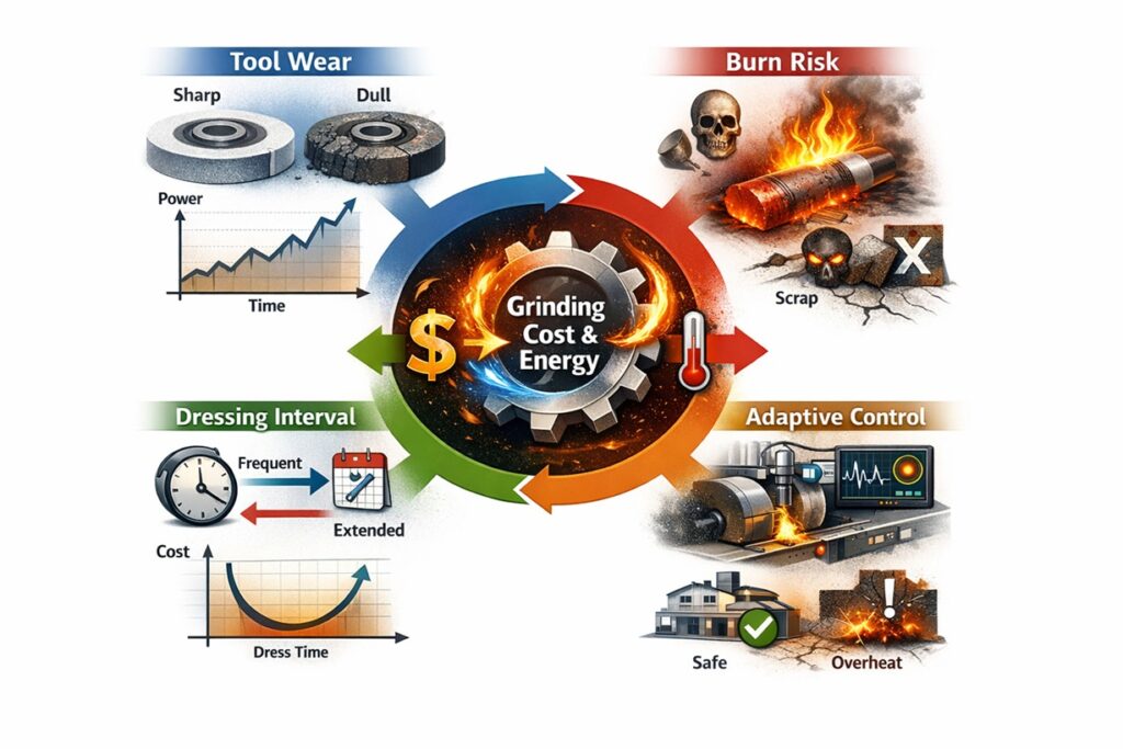
The condition of the grinding wheel’s surface, or its Topography, is the single most influential factor in determining the instantaneous power requirements of the grinding spindle. While kinematic parameters like vs and vw provide the framework for the process, the topography dictates the efficiency of each grain-workpiece interaction. A wheel with an “open” and sharp topography facilitates efficient chip formation, whereas a “closed” or dull topography forces the machine to spend energy on unproductive friction. In this context, Dressing is not merely a maintenance task; it is an energy-management strategy that directly regulates the facility’s utility expenditures.
Sharpness vs. Specific Energy (us)
The primary goal of dressing is to maintain a high Active Cutting Edge Density while ensuring that each edge is sharp. As a wheel grinds, the abrasive grains develop “wear flats” due to attritious wear. These flats increase the contact area between the grain and the workpiece, shifting the energy consumption from the “Chipping” regime to the “Sliding” regime.
Empirical studies show that as the cumulative wear flat area increases, the Specific Grinding Energy (us) can rise by as much as 200% to 300%. For a high-volume production line, this means the spindle must draw twice the power to achieve the same material removal rate (MRR’). This “Dullness Tax” is paid twice: first in increased electricity bills for the spindle motor, and second in the increased load on the chiller system to dissipate the resulting frictional heat.
The “Sawtooth” Power Signature of Dressing Intervals
In a production environment, energy consumption follows a Sawtooth Pattern. Immediately after dressing, the wheel is at its sharpest, and the spindle power draw is at its minimum. As the wheel dulls over the course of the Dressing Interval (fd), the power load gradually climbs. If the dressing interval is set too long to save on “wheel cost,” the cumulative energy waste from running a dull wheel often exceeds the savings from abrasive conservation.
Strategic cost optimization involves finding the “Economic Dressing Point”—the threshold where the cost of the next Joule of wasted energy exceeds the cost of a dressing cycle. By utilizing Adaptive Dressing triggered by a 15-20% increase in spindle power, manufacturers can ensure that the wheel always operates in its most energy-efficient state, maximizing both tool life and power economy.
The Cost of Dullness: Thermal Expansion and Scrap
Beyond the utility bill, a dull wheel topography introduces a Geometric Cost. Higher energy consumption leads to greater heat flux into the machine spindle and the workpiece. This thermal load causes Thermal Growth, which shifts the machine’s zero-point and results in dimensional inaccuracies (CPK degradation).
In precision industries like aerospace or EV driveline manufacturing, a dull wheel that consumes 10% more energy can lead to a 50% increase in dimensional scrap. Therefore, investing in high-performance dressers (CVD or Rotary Diamond) that maintain a constant sharpness is not just a technical choice—it is a financial maneuver to eliminate the most expensive energy of all: the energy that produces a part which must be thrown away.
The Topography Insight: “A dull wheel is like a tax that increases every minute you use it. You can try to save on wheel costs by delaying the dressing, but the machine will eventually take that money back through the power meter and the scrap bin. Optimal energy management begins with a sharp cutting edge.”
In the following section, we will analyze Thermal Management and Chiller Costs, examining how the energy that is not used for cutting creates a second wave of operational expenses in the cooling cycle.
7. Thermal Management and Chiller Costs: The Secondary Wave of Energy Expense
In the holistic energy audit of a grinding cell, a significant portion of the “hidden cost” is found not at the spindle, but in the Coolant Chiller System. Grinding is fundamentally a process of energy conversion; as discussed in previous chapters, the high Specific Grinding Energy (us) is largely converted into heat. This heat must be aggressively managed to prevent the machine structure and the metalworking fluid (MWF) from reaching critical temperatures. The electricity required to drive the refrigeration cycle of a chiller creates a “secondary wave” of energy expenditure that can equal or even exceed the primary power used for material removal.
Energy Partition (Rw) and the Cooling Load
The Energy Partition (Rw) represents the fraction of the total grinding energy that is conducted into the workpiece as heat. In conventional grinding with aluminum oxide wheels, Rw can range from 60% to 80%. This thermal flux into the part and the surrounding fluid dictates the Cooling Load that the chiller must compensate for.
From a cost-optimization standpoint, reducing Rw is the most effective way to lower chiller operating costs. By utilizing Superabrasives (CBN) or high-porosity vitrified wheels, the energy partition can be slashed to 20% to 30%. This dramatic reduction in heat flux directly translates to a lower duty cycle for the chiller compressor. In a facility with 50 grinders, this shift in abrasive technology can reduce the factory’s total utility bill by tens of thousands of dollars annually, solely through reduced refrigeration requirements.
The Economics of Chiller Efficiency: COP and Ambient Temperature
The efficiency of a chiller is measured by its Coefficient of Performance (COP). A chiller’s energy consumption is highly sensitive to the differential between the target coolant temperature and the ambient factory temperature. For every degree the ambient temperature rises, the chiller must work significantly harder to reject the process heat.
Many facilities run their chillers at unnecessarily low temperatures (e.g., 20°C) while the factory ambient is 30°C. This “Over-Cooling” forces the compressor into a high-energy regime. Strategic energy management involves setting the chiller to track the machine bed temperature or a stable “factory baseline” rather than an arbitrary low point. This Ambient-Tracking Strategy can reduce chiller power consumption by 15-20% without compromising the dimensional stability of the ground parts.
Thermal Residue and Dimensional TCO
The true cost of thermal energy includes the Capacity Loss due to stabilization time. If the energy management is poor, the machine must “rest” between heavy roughing passes to allow for thermal dissipation, or the first several parts of a shift must be discarded as the machine reaches its thermal equilibrium.
By investing in Heat-Exchanger Optimization and reducing the us at the source, the machine can maintain its “Thermal Steady-State” more consistently. This eliminates the “warm-up” waste and ensures that every part produced—from the first to the last—meets dimensional tolerances. In high-precision industries like automotive fuel injection or aerospace bearing manufacturing, the energy you save at the chiller is directly proportional to the scrap you save at the final inspection.
Thermal Strategy Insight: “Energy management in grinding is like managing a household budget. The spindle power is your rent, but the chiller cost is your utility bill. You can’t avoid the rent (cutting), but you can stop leaving the air conditioner on with the windows open (high Rw and poor thermal controls).”
In the concluding chapter, we will synthesize these technical findings into a Practical Roadmap for Energy & Cost Reduction, providing a step-by-step guide for facilities to achieve sustainable cost leadership through energy excellence.
8. Practical Roadmap for Energy & Cost Reduction
As we have established throughout this technical analysis, the path to energy excellence in grinding is not found in a single “silver bullet” solution, but through a systematic synchronization of Kinematics, Topography, and Fluid Dynamics. To transform these engineering principles into a sustainable competitive advantage, a facility must transition from a reactive “break-fix” mentality to a proactive Energy-Aware Manufacturing model. This concluding chapter provides a strategic roadmap for achieving significant cost reductions while enhancing process capability.
Phase I: The Energy Audit and Baseline Establishment
The first step in any cost-reduction program is to “make the invisible, visible.” Most facilities treat electricity as a fixed overhead cost rather than a variable process parameter. A comprehensive Energy Audit must be conducted to establish the baseline for each machine cell. This involves measuring the Idle Power (Pidle) versus the Active Grinding Power (Pgrind) across multiple shifts.
By utilizing high-frequency power sensors on the spindle and auxiliary systems, engineers can calculate the Specific Energy per Good Part. This metric is the “North Star” for optimization; it identifies which processes are suffering from the “Size Effect” (as discussed in Chapter 3) and which machines are hemorrhaging money through inefficient chiller and pump operations.
Phase II: Low-Cost Parameter Optimization
Before investing in new hardware, the most significant “low-hanging fruit” is found in the Process Kinematics. As demonstrated in Chapter 4, increasing the work speed (vw) while maintaining or slightly reducing wheel speed (vs) can radically lower the specific grinding energy (us).
- Increase Chip Thickness: Adjust feed rates to move away from the high-friction “Sliding” regime.
- Optimize Dressing Overlap: Ensure the wheel topography is open and sharp (reducing Rw).
- VFD Integration: Install Variable Frequency Drives on coolant pumps to modulate flow based on real-time process demand.
Phase III: Strategic Capital Investment
For facilities aiming for “Zero-Waste” status, the final phase involves investing in disruptive technologies like Electrolytic In-process Dressing (ELID) or Laser Dressing systems. While these require high upfront CAPEX, their ability to eliminate the Non-Productive Time (tnp) of dressing cycles and maintain a perfectly sharp wheel (minimizing us) provides an unbeatable OPEX advantage in the long run.
Furthermore, the transition to MQL (Minimum Quantity Lubrication) systems should be evaluated for appropriate applications to completely eliminate the energy-heavy infrastructure of flood cooling and chillers. In high-volume automotive gear grinding, the removal of the chiller system alone can reduce the machine cell’s energy footprint by over 35%.
Concluding Vision: “Energy efficiency in grinding is the ultimate measure of process mastery. When we reduce the Joules consumed per part, we aren’t just saving pennies on the electricity bill; we are stabilizing the metallurgy, extending the life of our tools, and reclaiming the capacity of our machines. Profitability is the byproduct of thermal and energy excellence.”
Conclusion: The Future of Grinding Economics
In a manufacturing world increasingly defined by Sustainability (ESG) and radical cost competition, the ability to control the energy flow of the grinding process is the hallmark of a world-class operation. By applying the principles of the “Size Effect,” optimizing kinematics, and managing the secondary wave of chiller costs, manufacturers can unlock hidden potential within their existing assets.
This report has provided the engineering foundation and the strategic roadmap to move from an “energy-blind” process to an “energy-optimized” competitive engine. The Joules you save today are the profits you secure for tomorrow.
References & Internal Technical Resources
Primary Engineering & Scientific References
- • Malkin, S., & Guo, C. (2008). Grinding Technology: Theory and Applications of Machining with Abrasives. Industrial Press Inc.
- • Rowe, W. B. (2014). Principles of Modern Grinding Technology. Academic Press.
- • Marinescu, I. D., et al. (2013). Handbook of Machining with Grinding Wheels. CRC Press.
Internal Deep-Dive Series: Energy & Process Optimization
To further explore the advanced strategies for grinding energy efficiency and cost reduction, please refer to the following specialized modules from our technical roadmap: